5
$\begingroup$

I have a simple skewed cube (see below) and I would like move "face A" along the plane of "face B" (the direction of the arrow) to simply extend the dimension of the cube in that direction.
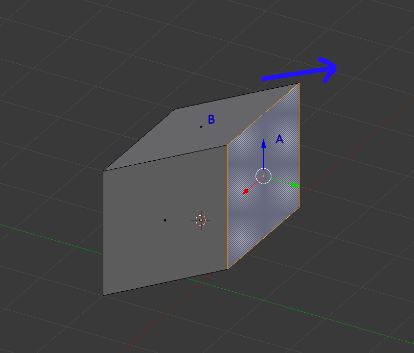
cube with faces labled

If I try selecting "face A" and pressing G Y, the face moves along the global Y axis, not along the plane of "face B". I've also tried various combinations of Local coordinates (eg G Y Y) with no luck.

I also tried extruding the face (e.g. E Y) but found the same issue. If extrusion actually is the answer, that's fine as I could just dissolve the internal edges once extruded.

Some background. I'm creating a number of simple geometric shapes I then render out (in orthographic projection) as 2D isometric building "blocks". Other shapes include basic ramps, triangular corners etc. Often, I need to make small adjustments to dimensions to get the exact rendering output I need.

$\endgroup$
4
  • $\begingroup$ The times I needed to do something like this, I found workarounds using the array modifier, but I'll wait to post it in case someone has a more direct method. Meantime, I think I'd find it helpful to have a bit more information about exactly what you want to use this maneuver to accomplish, and the context. I might use one approach to solve this problem if it is a discrete mesh, but another if it is some part of a more complex object. $\endgroup$
    – brasshat
    Commented Dec 16, 2015 at 3:47
  • $\begingroup$ This is a bit long, but I usually go into Normal transform orientations, select the edge that parallels the direction you want to move the face, and save that orientation as a new transform orientation. Then you can select the face and hit [Y] twice to move along that axis. $\endgroup$
    – PGmath
    Commented Dec 16, 2015 at 4:00
  • $\begingroup$ @brasshat, good point, I've added more background. The shapes are simple and not part of bigger meshes. I'm interested in any solution, I find Blender always has less obvious solutions that still do the job. $\endgroup$
    – Ash
    Commented Dec 16, 2015 at 4:04
  • $\begingroup$ @PGmath, thanks for the reminder about custom orientations. That would probably get the job done, I'll give it a try. As brasshat said, I wonder if there is a more direct way, but knowing Blender, possibly not. $\endgroup$
    – Ash
    Commented Dec 16, 2015 at 4:07

3 Answers 3

4
$\begingroup$

I was able to achieve this by creating a custom orientation as suggested by @PGmath. If there is a more direct approach please post an answer as it seems like there should be.

Anyway here's how to do it:

  1. Go to edit mode and select an edge that is in the direction you want to move the face. In my case this was the edge in the diagram below the label 'B'.

  2. Change the Orientation to 'Normal' and notice the X/Y/Z guides now conform to that edge.

  3. Open the Properties window (press N) and scroll down to find "Transform Orientations".

  4. Click the + button to create a new orientation based on the current selected edge/orientation.

  5. Over on the left hand tools panel, scroll to the bottom and in 'Create Orientation' give the custom orientation a name.

  6. Now, select the custom orientation in the Orientations drop-down at the bottom of the 3d view.

  7. Go into face select mode and select face A.

  8. Type G Y Y and move the face along the plane as required. (Pressing Y twice uses the custom orientation, once only uses the global orientation.)

Listen to the little robot man in this youtube video if you need more info on creating a custom orientation.

That works, but far easier would be to just select the face representing the plane to move along (B) and somehow tell Blender to constrain moving faces/edges/vertices along that plane.

I don't have the time or knowledge to write that myself, if anyone does it would be appreciated.

$\endgroup$
2
$\begingroup$

OK, based upon the given situation, the way I'd approach this is to use what I term "helper geometry". To help the explanation, I'll call the face of the cube in the original illustration opposite face A, face "A1". I'd extrude either the edge between faces A and B, or one of the constituent vertices to the approximate desired new location of the face, constraining the translation to movement along the y and z axes by locking movement along the x axis. When the vertex was extruded, I would create an edge between that newly extruded vertices and one of the vertices of the edge A1-B. I'd orient the model to a side view perpendicular to face A, and adjust the extruded vertex so the line from that vertex to edge A1-B passed exactly through the edge on A-B. Changing the selection mode to face select, I'd select face A and move that face so that the edge A-B of the cube was aligned with the extruded vertex, and delete the line between the extruded vertex and the vertex on edge A1-B.

This technique would work even if the cube was not aligned with any of the axes of the scene.

$\endgroup$
1
  • $\begingroup$ Thanks for the answer. It's useful to have more than one solution here for future reference. Both solutions are not exactly streamlined (not our fault), but I found the custom orientation approach easier to follow and understand so I used that. $\endgroup$
    – Ash
    Commented Dec 16, 2015 at 6:32
1
$\begingroup$

I would use Edge Slide or Vertex Slide.

This allows you to move along an existing edge. The shortcut is double tap G. In this option, you will find that you can "slide" or move along an existing edge, but can not go beyond the edge you are on. So you can then press Alt to extend, or type C to keep the option enabled.

This will allow you to move beyond the selected edge. Once you are able to place a vertex along the continuation of an edge, you can then use it as a reference to move or copy the geometry you wanted to move there.

$\endgroup$

You must log in to answer this question.

Not the answer you're looking for? Browse other questions tagged .