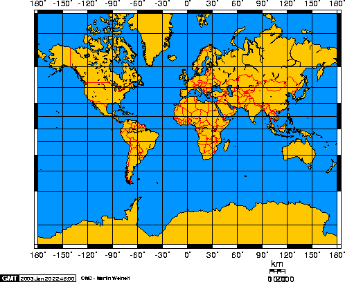
I'm trying to unwrap a UV Sphere and I can't seem to get a perfect Mercator projection. What process should I follow to get a perfect UV unwrap that looks like the black grid lines in this image?:
3 Answers
Update:
Newer versions of Blender now come with a Generate UVs checkbox (that can do as the name says and provides pretty decent maps) when adding a new mesh for most of the objects. Simply access this from the F6 menu or the toolshelf. This option is only available when generating a new object. The layout is below, still not perfect but useful nonetheless .
Add a UV Sphere to the scene and select an edge with AltRMB, next enter Face selection mode and select a face near the edge you marked. Next hit A to select the entire sphere and hit U > Follow Active Quads.
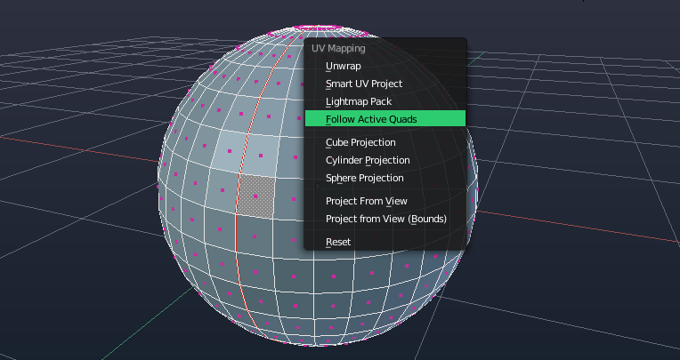
Note the grayed face near the middle of the sphere along the edge, this means that it had been selected before you selected the entire sphere and this is similar to what you should have done.
After unwrapping, you should get a huge UV map in the Image Editor. Transform it as desired, I would recommend aligning one corner of the map to a corner of the image and scaling it via the 2D Cursor.
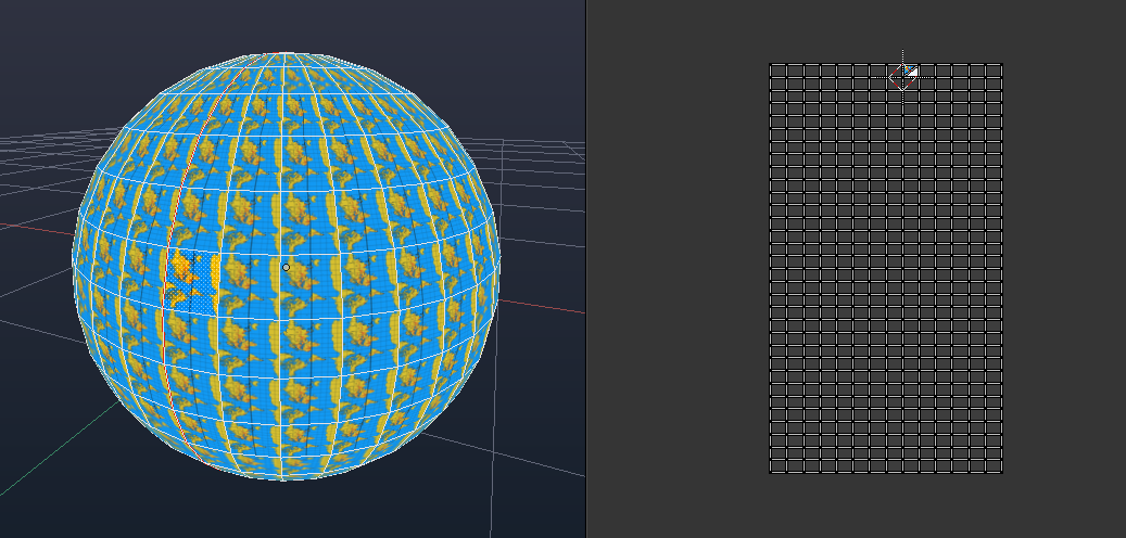
A perfectly unwrapped sphere sans exponentially spaced UVs which aren't possible unless you tweak the map afterwards or modify the object's geometry.
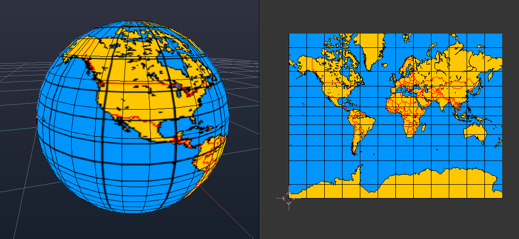
You might notice a sharp seam near the top of your sphere where the texture stops. This is caused by the geometry of the sphere as the top vertices merge into a single point and the unwrap method basically ignores it.
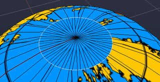
To fix, just get an edge ring as close as you can to the middle vertex so that it won't be noticeable.
-
$\begingroup$ What about a script taht simply sqares the v coordinates? $\endgroup$ Commented Oct 13, 2013 at 9:10
-
$\begingroup$ I just found the topic, because I have to solve the same problem and I could follow the tutorial that far but I have one more question. You write "Transform it as desired, I would recommend aligning one corner of the map to a corner of the image and scaling it via the 2D Cursor." But how does this work? How can I align the corner of the map to the corner of the image? Thanks for help! $\endgroup$– user1589Commented Nov 11, 2013 at 20:36
-
1$\begingroup$ @helpMePlease I mean that you can select the entire UV by pressing A and then translate a corner of it into a corner of the canvas over the image. Once there, go to the header of the UV window and change the pivot point (a box with a blue circle in it) to 2D cursor. You can then scale the image from that point of the canvas, it's completely optional but makes scaling/adjusting the image a bit easier $\endgroup$– iKlsRCommented Nov 11, 2013 at 20:42
-
$\begingroup$ To avoid the problem at poles, you can create a sphere that is all quads. To do that, create a circle. Enter vertex mode and delete the top half of the circle, but leave the leftmost and rightmost vertices. Select a view where the circle looks like a half line (Numpad 3 did this in my case), select all and click Spin. Select -360d as angle and adjust other parameters as needed. Enter edge mode, uncheck Limit Selection to Visible, and shift+alt+click on the starting edge (the number of selected vertices should double). Now remove doubles. Done, you have a sphere where even the poles are quads. $\endgroup$ Commented Jun 11, 2015 at 9:26
-
$\begingroup$ @PedroGimeno I think you should write an answer if you can. Thanks. $\endgroup$– iKlsRCommented Jun 11, 2015 at 14:17
Mercator Projection Addon
Install the addon.
To use the addon, have a spherical mesh in edit mode. From Mesh > UV unwrap menu choose Mercator Project
Set the minimum and maximum latitudes of your mercator map, in the example image world map that's from -69.814 degrees (south), to 85 degrees north. The code selects all verts within this range (inclusive) and maps a UV.
The poles have an infinite mapping, and hence are not mapped.
Currently the object's origin needs to be in centre.
Will expand more later.
-
$\begingroup$ that looks awesome ! A good addition would be a way to calculate the min/max latitudes from the image's aspect ratio like I did with my script $\endgroup$ Commented Sep 25, 2017 at 16:57
-
$\begingroup$ @ChameleonScales Actually used an edited version of your code, except selected a point on equator, and inverse function to calculate for north and south, (instead of assuming equivalence). I'm making a suite of geographic projections using this tome $\endgroup$ Commented Sep 25, 2017 at 17:11
-
$\begingroup$ (long link) continued... Might put together a reverse UV that makes a sphere mesh from the map, which would allow for creating the correct N and S latitudes when creating the mesh. (eg those you chopped off) $\endgroup$ Commented Sep 25, 2017 at 17:11
As you know, a full Mercator projection expands vertically to infinity, so it always has to be truncated on the latitude and different images use different truncation angles. So I made 2 scripts :
- one that determines the truncated angle based on the aspect ratio of your image (in case you don't already know that angle). Of course your image must not have any added border (like the black and white checker border on the image you posted in your question).
- and one that distorts your UV map from an equirectangular projection to a Mercator projection.
Note that some images are not even truncated at the same angle between North and South. For those you have to extend the canvas of the image so the equator is in the middle.
Here's how to do the whole thing :
- Open Blender from the terminal (e.g on Windows run cmd and enter
blender.exe
) - open this file from it :
- There's an empty mesh object named "Sphere". While staying in edit mode, create a UV sphere (this way it already has the material assigned to it). Tweak the number of segments and rings to whatever you want. For your first time I recommend matching the grid on the image to really see that it works, which would be 24 segments and 12 rings. And don't generate UVs.
- in the object named Truncator there are 3 modifiers. Expand the 2nd one and in the "Steps" property, enter the same number as the number of segments in your sphere (like 24).
- If you already know the latitude angle at which your image is truncated, skip this step. If you don't, read the description of the script named "Truncated angle calculation" in the Text Editor and once you've done that, run it and look at your terminal.
- now that you know the truncated angle from the poles, copy it in the X rotation of the Empty object named "Truncated angle" (currently set to 12.5°)
- add a boolean modifier to the sphere :
- Operation : Difference
- Object : Truncator
- Solver : Carve
- select the first layer of the scene to hide the Truncator
- apply the boolean modifier
- in Edit mode, select everything by pressing A twice and do a Ctrl+V > Remove Doubles
- delete the vertex at the center of the sphere
- select everything and do a U > Sphere Projection :
- Direction : Align to object
- Correct Aspect : unchecked
- if one or several faces of your UV map are moved to the other side on X, select them, press Y to separate, then G and move them anywhere outside, then select the edges that should connect to the grid and hit V and left click to Stitch.
- go in Object mode and Material shading
- in the Text Editor select the other script, named Mercatorizer and read its description.
- run the script
- go in edit mode and zoom on the timage to see that the UV map matches the grid of the image.
Now you can do this with any image and any sphere resolution.
Have fun Mercatorizing !
U
> Sphere projection or Cylinder projection work? $\endgroup$