(Using Blender 4.2.1)
Approach and results
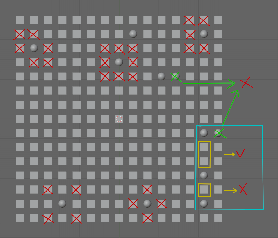
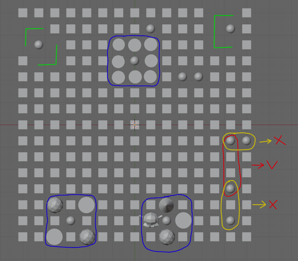
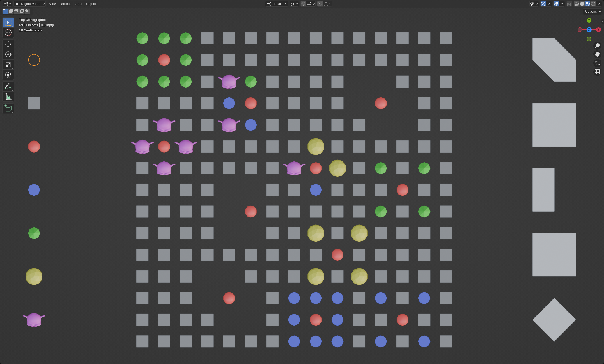
Two collections are defined, one with the different patterns of points around a sphere (see next figure right side), one with the different objects to spawn on a grid (see next figure left side). The location in the grid of a pattern center is randomized using a Distribute Points on Faces node whose Distribution Method is set to Poisson Disk to avoid overlaps. Patterns are used to delete points around a sphere, to instance the same object around a sphere, and to instance different objects around a sphere. This behavior is also randomized.
Resources

(Blender 4.2.1+)
GeometryNodes modifier
Overview
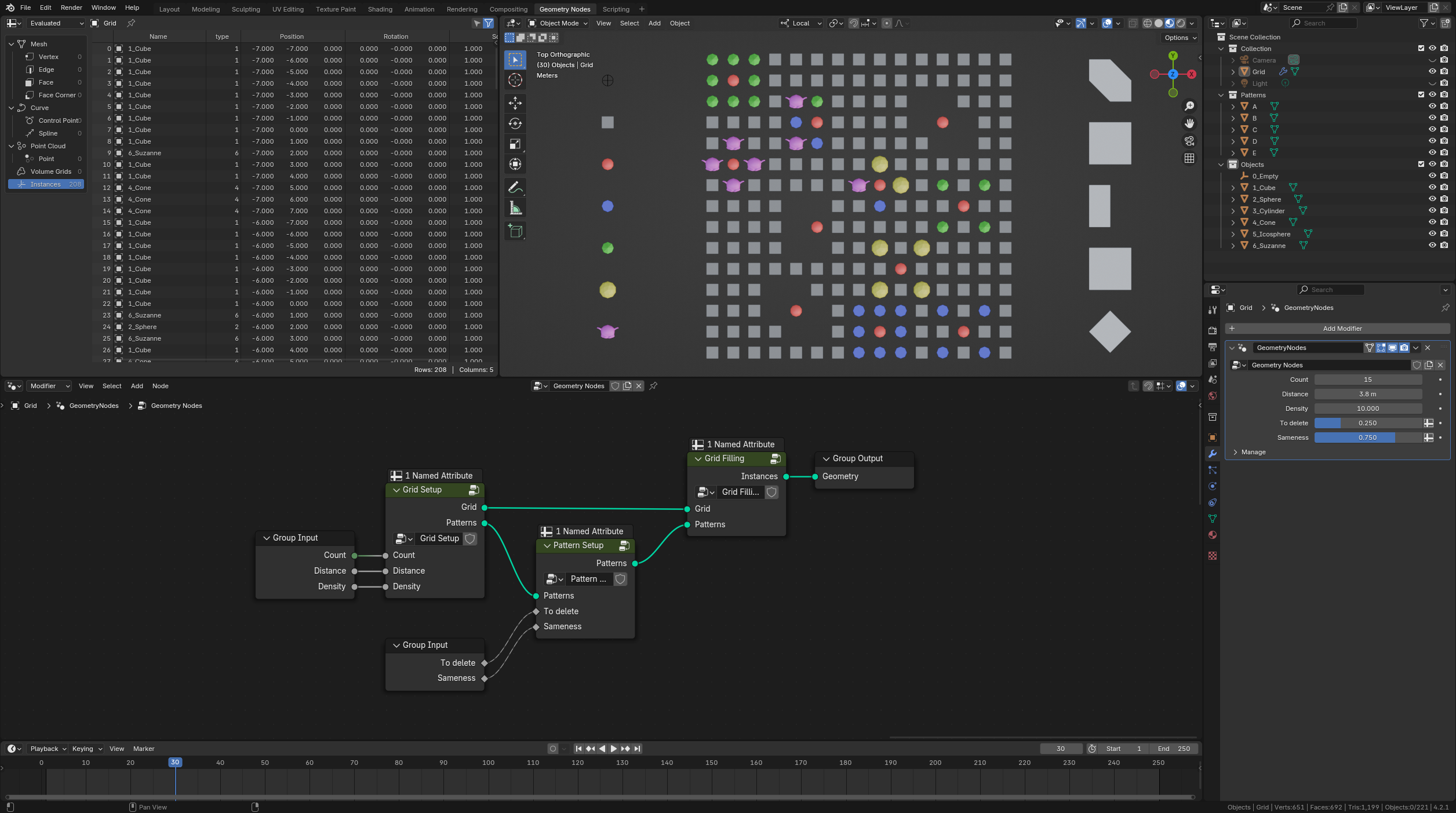
Scene setup:
- Grid: default object to which the GeometryNodes modifier is attached.
- Patterns: collection of the different patterns. Each is made from a 3x3 grid modified in Edit Mode to delete the central point, as well as some border points. Duplicating a pattern increases its probability to be spawned. The size of this collection is managed dynamically. Order in this collection is irrelevant.
- Objects: collection of the different objects to spawn. Duplicating an object increases its probability to be spawned. The size of this collection is managed dynamically. Order in this collection is crucial. Consequently, names are edited to enforce the alphabetical sorting.
- Object of index 0 is never spawned. It is used to mark where grid points are deleted.
- Object of index 1 is the object spawned everywhere initially.
- Object of index 2 is the object spawned at the center of a pattern.
- Objects of index 3 and more are spawned at the border of a pattern. Consequently, this collection must contain at least 4 objects.
GN input parameters:
- Count: number of rows and columns of the grid (minimum 3).
- Distance: Minimal distance between the centers of two adjacent patterns.
- Density: Factor controlling the probability to spawn a pattern at a grid point position. Too large values are ineffective once the grid is fully packed based on the minimal distance.
- To delete: Factor controlling how many pattern points are deleted before spawning objects. 0 yields no deletion. 1 yields no spawned objects.
- Sameness: Factor controlling how many patterns are made with the same object. 0 yields random objects everywhere. 1 yields the same object per pattern.
GN main graph:
The main process is made of 3 steps coded as Group Nodes:
- Grid Setup: initializes the grid and where patterns would be spawned.
- Pattern Setup: randomizes each pattern behavior (deletion, same object spawned, different objects spawned).
- Grid Filling: spawns objects on the grid according to the patterns.
Grid setup
Initialization of the grid and where patterns would be spawned:
 Dark red nodes:
1. The step of the Cartesian Grid is 1. So its width and height are 1 less than Count, its number of rows and columns.
2. The attribute stored in Point domain named "type" is set at 1, the index of the object spawned everywhere initially.
Dark green nodes:
3. To not spawn patterns centered on the grid border, interior edges are flagged as True by counting how many faces they belong to. Border edges are connected to only 1 face ; interior edges are connected to 2 faces.
4. This flag is transferred from the Edge domain to the Point domain using a Capture Attribute node. "Averaging" of boolean values is such that this flag is True at a point if and only if it is True for all the edges connected to this point. So it is False for all the points along the grid border.
Dark blue nodes:
5. There is no node to distribute points on points randomly. Consequently, a Distribute Points on Faces node is used instead. Setting its Distribution Method to Poisson Disk combined with the Distance Min parameter is the way to randomize positions on the grid with a constraint on how these are spaced. How many patterns would be spawned is controlled by the Density Max parameter. To create different cases, the Seed can be animated with the active Frame number.
6. It is to notice that points generated at step 5 are almost never colocated with grid points. So they are moved using a Set Position node. Their new location is recovered from the nearest grid point with a first Geometry Proximity node.
Dark pink nodes:
7. The "type" of a grid point colocated with a pattern center is updated using a Store Named Attribute node whose Selection mask is checking the distance between this grid point and the nearest pattern center, returned by a second Geometry Proximity node. Border grid points are excluded at this time.
8. The "type" is set at 2, the index of the object spawned at the center of a pattern.
Dark grey nodes:
9. Patterns are spawned centered on the points updated at step 6 using an Instance on Points node. Border grid points are excluded once again. Activating the Pick Instance parameter, successive patterns are picked from the Instance collection.
10. Instances are recovered as separated objects from the collection "Patterns" using a Collection Info node with the parameter Separate Children checked. The world position of each pattern is irrelevant because the Reset Children parameter is checked also.
Pattern setup
Randomization of each pattern behavior:
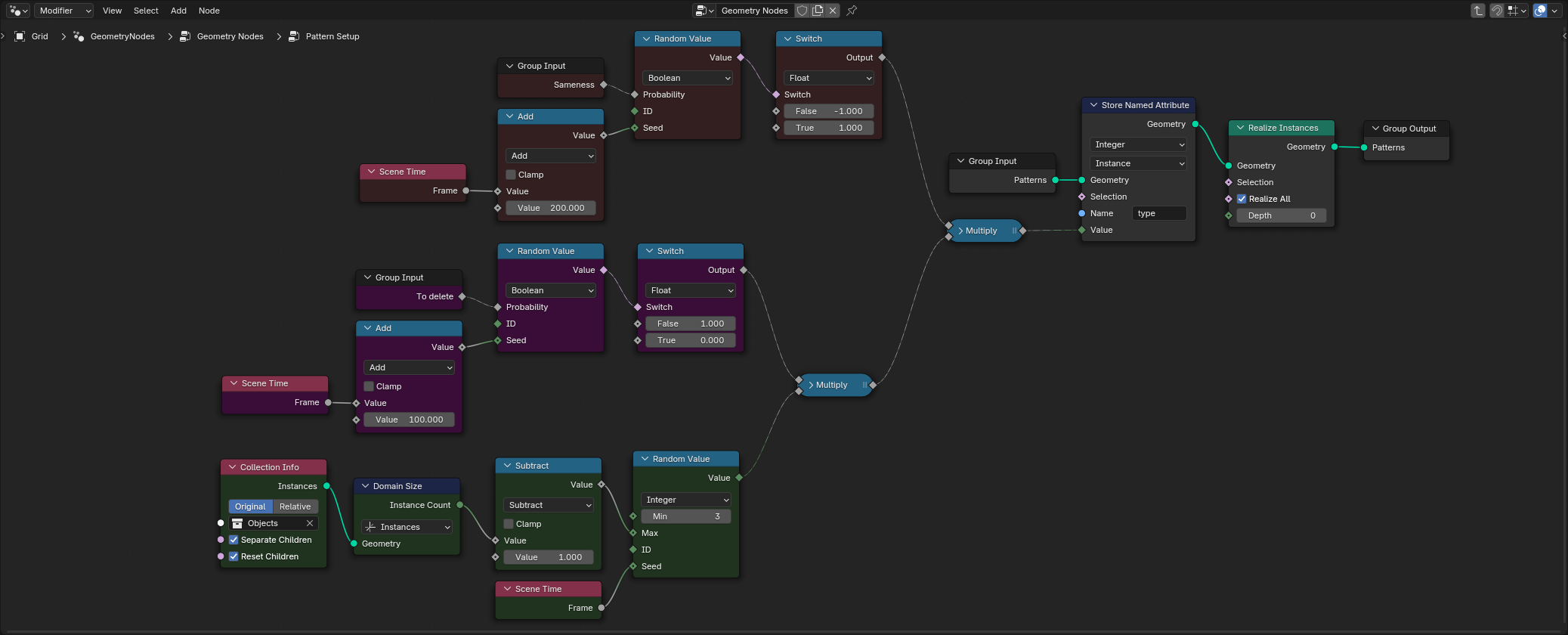 Dark green nodes:
1. The default behavior of a pattern is to spawn the same object at each of its vertices, yielding homogeneous patterns. The index of this object inside the collection "Objects" is drawn randomly from 3 (because objects with index 0, 1 and 2 are reserved for specific tasks) up to the last object in the collection.
2. This last value is computed as 1 less than the collection size, recovered through a Domain Size node set in Instances domain. To get it right, the parameter Separate Children of the Collection Info node must be checked.
3. The Seed of the random process is animated with the active Frame number.
Dark pink nodes:
4. The object with index 0 is attributed to grid points to be deleted. A Boolean probability is drawn for each pattern, controlled by the input factor "To delete", and by the active Frame number. It is to notice that this number is arbitrarily offset by 100 to unsynchronize the successive random processes.
5. A Switch node is inserted to explicitly convert True values to 0, and False values to 1. A Multiply Math node is then used to nullify, or to keep unchanged, the object index drawn at step 1.
Dark red nodes:
6. Objects spawned on patterns with negative object index are randomized, yielding not homogeneous patterns. A Boolean probability is drawn for each pattern, controlled by the input factor "Sameness", and by the active Frame number. It is to notice that this number is arbitrarily offset by 200 to unsynchronize the successive random processes.
7. A Switch node is inserted to explicitly convert True values to 1, and False values to -1. A Multiply Math node is then used to keep unchanged, or to make negative, the object index drawn at step 1.
Dark grey nodes:
8. Eventually, an object index (positive, null or negative) per pattern is stored as an attribute named "type". It is to notice that the Store Named Attribute node is set in Instance domain.
9. To get the final position of the vertices of each pattern, and to propagate the attribute "type" from Instance to Point, a Realize Instances node is used.
Grid filling
Instantiation of objects on the grid according to the patterns:
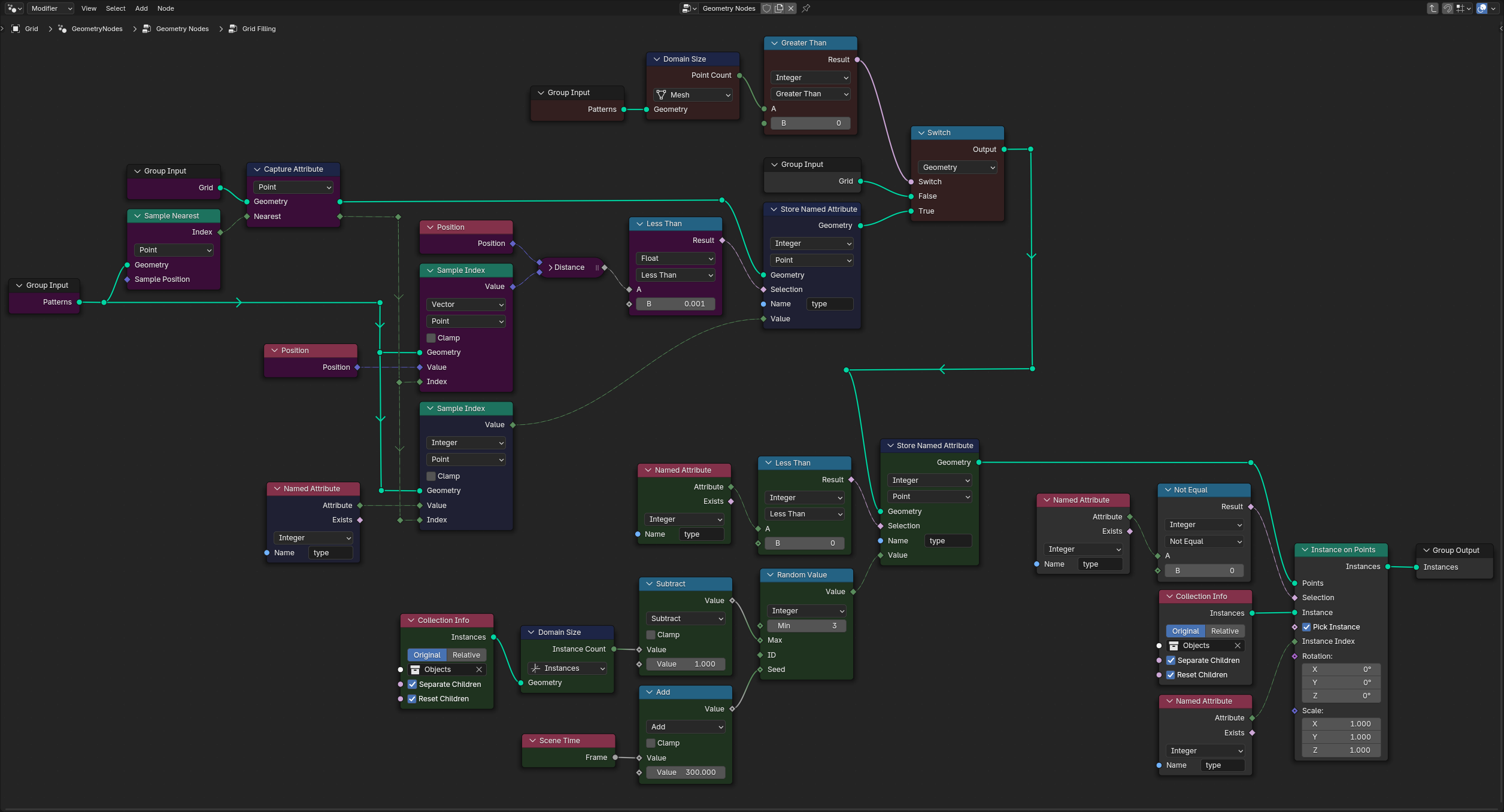 (to be documented...)
Discussion

