(Using Blender 4.2.1)
This proposal is an adaptation of the post Passing GeoNodes attribute to Shader frame offset.
Approach
One way to proceed is to set up 3 parts:
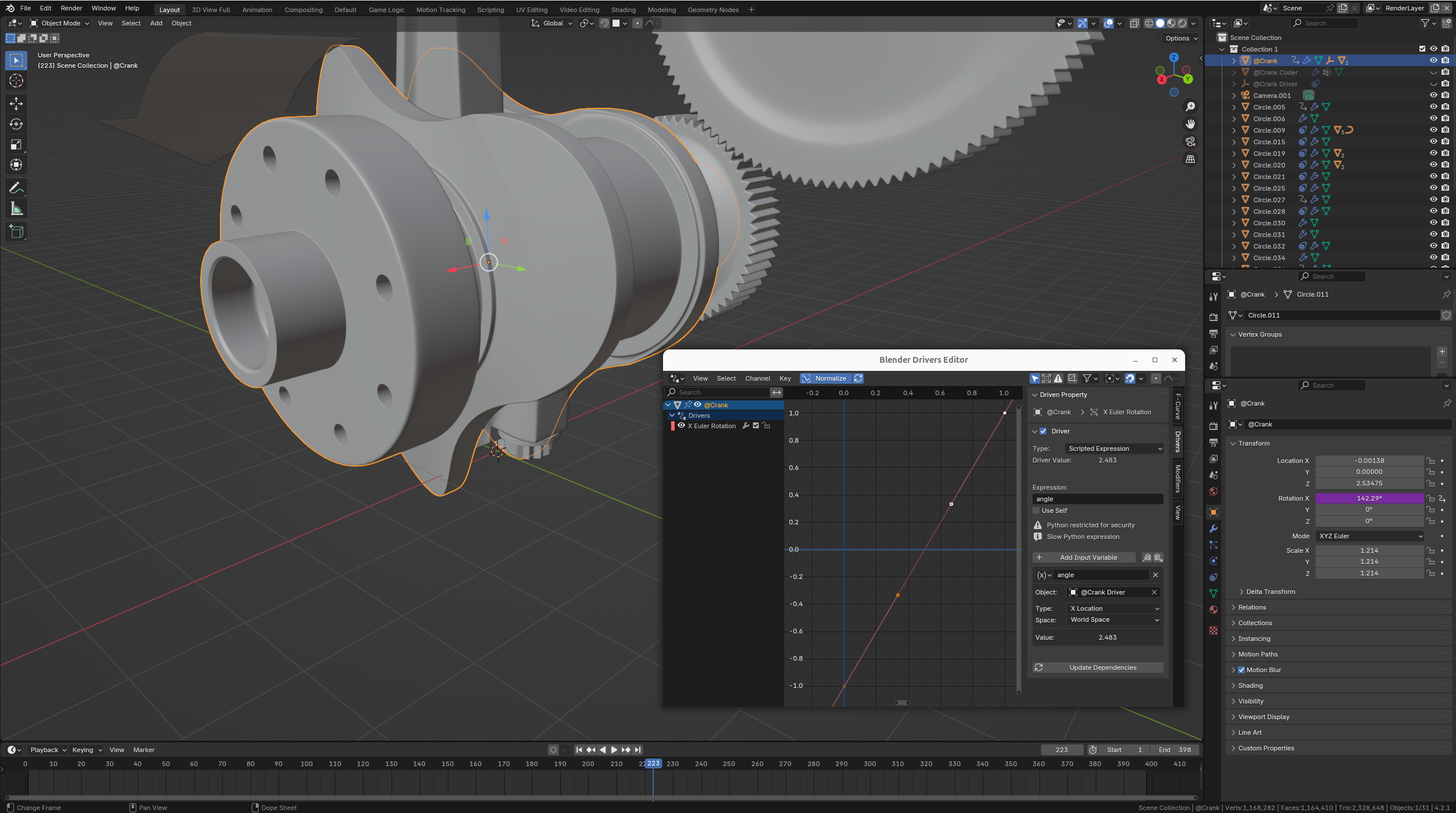
- The original object (named "@Crank") with no GeometryNodes modifier, but instead with a Driver controlling its property Transform - Rotation X.
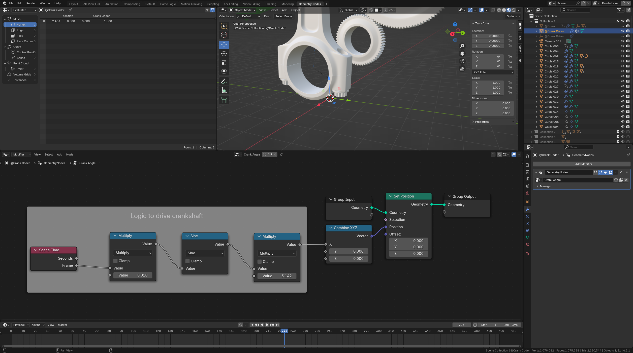
- A single vertex mesh (named "@Crank Coder") whose X position is set by the GeometryNodes modifier originally attached to the "@Crank" object.
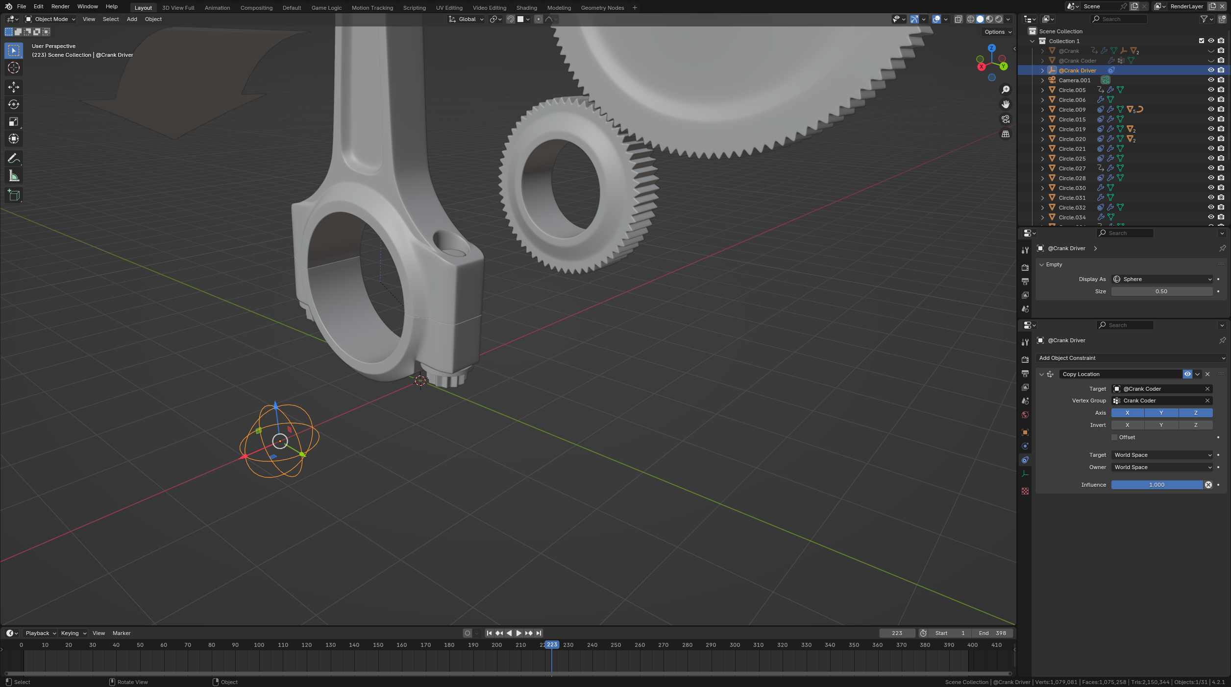
- An Empty (named "@Crank Driver") making the communication between the two previous objects
- by copying the "@Crank Coder" position (read/pull/receive),
- by providing the value of the rotation angle to the "@Crank" Driver (write/push/send).
Crank Coder set up
 1. In Object Mode, add an object made of one vertex using the menu entry Add>Mesh>Single Vert>Add Single Vert. Its position is irrelevant. Because only one value is coded, one vertex is enough.
2. Add a GeometryNodes modifier to this object. Then copy & paste the nodes of the original "Move crank" graph.
3. Replace the Transform Geometry node with a Set Position node.
4. At this stage, the X coordinate of this vertex is equal to the targeted angle of the crank shaft animated with the Frame number. However, it is to notice that only the position of the vertex is updated. The object's origin remains at its creation location defined at step 1. To use this vertex as a moving point in the definition of a constraint, the documentation explains that "(...) the constraint will target the median point of this vertex group instead of the object’s origin".
5. Consequently in Edit Mode, in the Object Data Properties panel, add a Vertex Group (named "Crank Coder") and Assign after selecting it the single vertex to this group. With only one point, the group median point is this point.
Crank Driver set up
 6. Add an empty object using the menu entry Add>Empty>Sphere. Its position is irrelevant.
7. Add a Copy Location constraint to this object. Set the Target to the "@Crank Coder" object created at step 1, then the Vertex Group to the "Crank Coder" group created at step 5.
8. At this stage, the animation shows the empty sliding along the X axis, colocated with the moving vertex.
Crank set up
 9. In the Object Properties panel, press RMB over the Rotation X property then select the menu entry Add Driver.
10. In the Drivers Editor, rename the variable to "angle" for example. Set the empty as driving Object (i.e. "@Crank Driver" here).
11. Check that Type is set to "X Location" (the coordinate chosen to encode the crank shaft angle in the GeometryNodes modifier at step 3), and that Space is set to "World Space".
12. Play the animation.
Resources

(Blender 4.2.1+)


