0
$\begingroup$

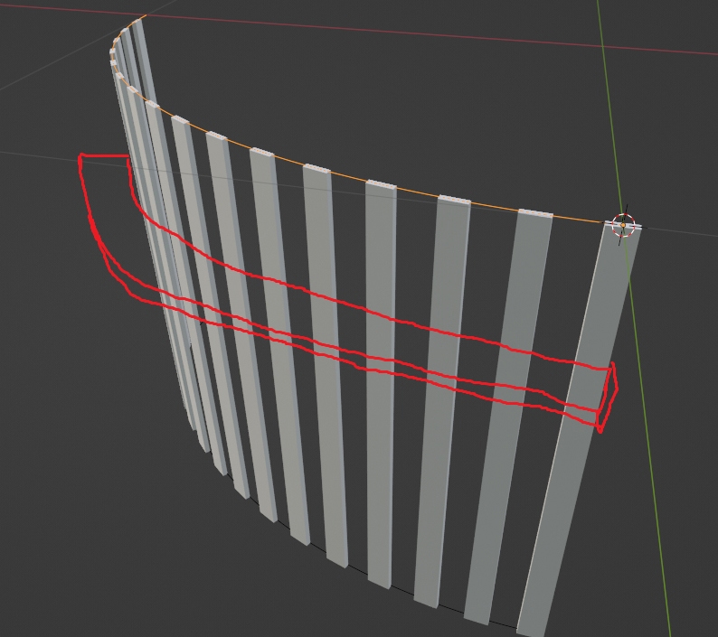
I have this array of bars, which is created by using an array modifier and then a curve modifier. Note that each bar is tilted backwards by 10 degrees.

enter image description here

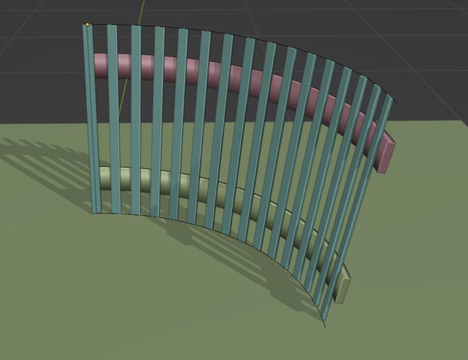
I would now like to add a few new pieces at different heights, such that they follow the general shape of the array of bars, like this:

enter image description here

How can I do this?

Things I tried, but didnt work:

  • Trying to use a boolean modifer to cut out the shape.
  • Trying to use knife project.

(Note, what I currently have was actually created by using "instancing" on each face of a helper plane, which prevents each bar from deforming.)

$\endgroup$
4
  • $\begingroup$ Can't you use the curve? It (or a copy of it) can be extrude in the properties panel or with Geometry Nodes. $\endgroup$
    – Blunder
    Commented Apr 15 at 22:13
  • $\begingroup$ @Blunder I need to somehow extract what the correct radius of curvature is, depending on the distance from the top. The curve shown is only the correct radius for the very top position. Further down from the top I would need a curve with a different radius of curvature. $\endgroup$
    – teeeeee
    Commented Apr 16 at 1:03
  • $\begingroup$ That's true. But since you have the top and bottom arcs you can interpolate the radius. I guess you want something like this (i.sstatic.net/GrWH6wQE.jpg)? $\endgroup$
    – Blunder
    Commented Apr 16 at 17:04
  • $\begingroup$ @Blunder yes exactly. How did you do it? How to automatically give the central bands the correct radius? $\endgroup$
    – teeeeee
    Commented Apr 16 at 18:24

1 Answer 1

2
$\begingroup$

example with 2 horizontal rails

Since you have a top arc and a bottom arc, you can use them to create a copy that interpolates the positions of the control points so that the new arc appears between them. In other words: the control points' position is mixed between the top position and the bottom position. The factor thus determines the height of the new arc. It's similar to a shape key.
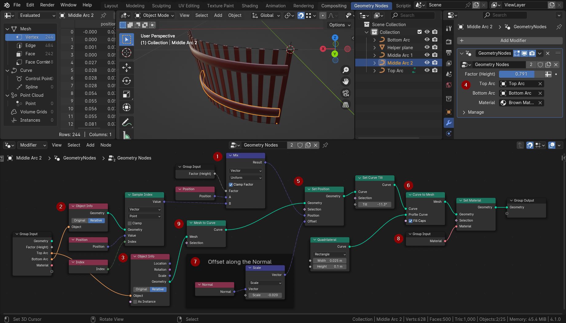
geometry node tree

The Mix node (1) mixes the positions of the two arcs (2) and (3). You can define them and the Factor in the modifier's setting (4). The labels of the Group Input node can be changed in the side panel of the Geometry Nodes editor (press key N with the mouse in the editor to open it).

The Set Position node (5) adjusts the position of the control points with an offset along the Normals (7) so that the rails are in front or behind the slats.

With Curve to Mesh (6) you can give the new arc some geometry. Of course, you also could instance other objects on its points, similar to the Array and Curve modifiers that you use.

The material (8) must be set by a Set Material node. If you drag it to a Group Input node you can define the material in the GN modifier settings (4).

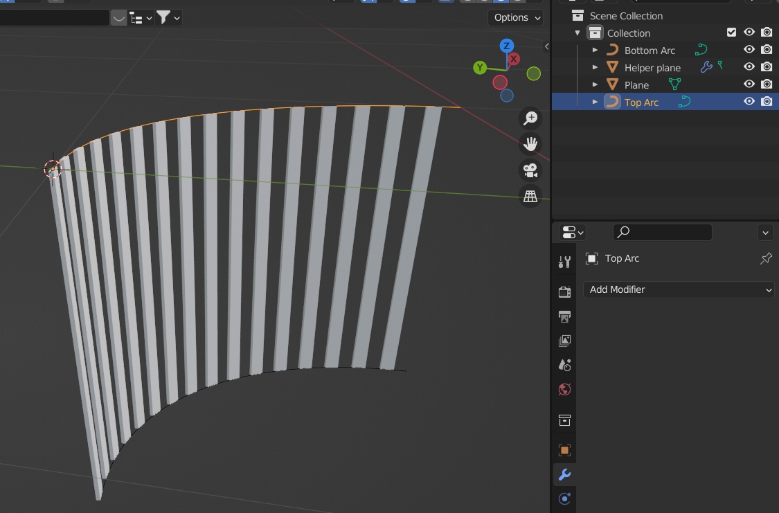
For some reason I don't know, the Top Arc curve is considered a mesh and not a curve. It's a curve in the outliner, but it can be converted implicitly to a mesh when it has shape keys, or in the Properties > Geometry section the Bevel/Extrude settings are used. That's not the case here, but Blender still complains that the Top Arc is a mesh, while the Bottom Arc is a real curve. (If there is an error you will see a little (!) in the top right corner of the node. Hover it to see the error message.). That's why we use the Mesh To Curve node (9) to ensure that the curve is really a curve and has not been implicitly converted to a mesh for some reason.

$\endgroup$
1
  • $\begingroup$ Nice answer. I appreciate your detailed explanation, thank you. I was thinking there might be a modifier that works directly in such a situation ("shrinkwrap" or "surface deform" sounded like they might be appropriate). But geometry node is so much more powerful. $\endgroup$
    – teeeeee
    Commented Apr 18 at 9:47

You must log in to answer this question.

Not the answer you're looking for? Browse other questions tagged .