2
$\begingroup$

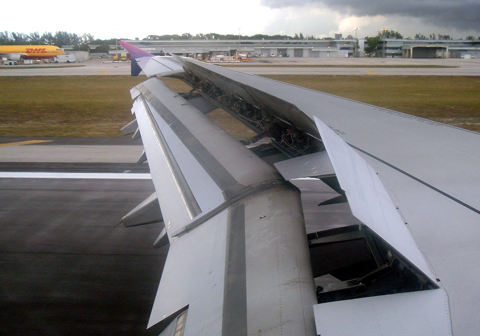
I'm trying to model an airplane wing. I've already done the main wing body and the flaps, and I'm on my way to model the spoilers (the plates extending upwards):

airplane wing on landing

How can I go about extruding these plates out of the wing body? I've tried extruding these edges but they get into a weird orientation and I can't align it with the wing's surface. How can I do this maintaining a good topology?

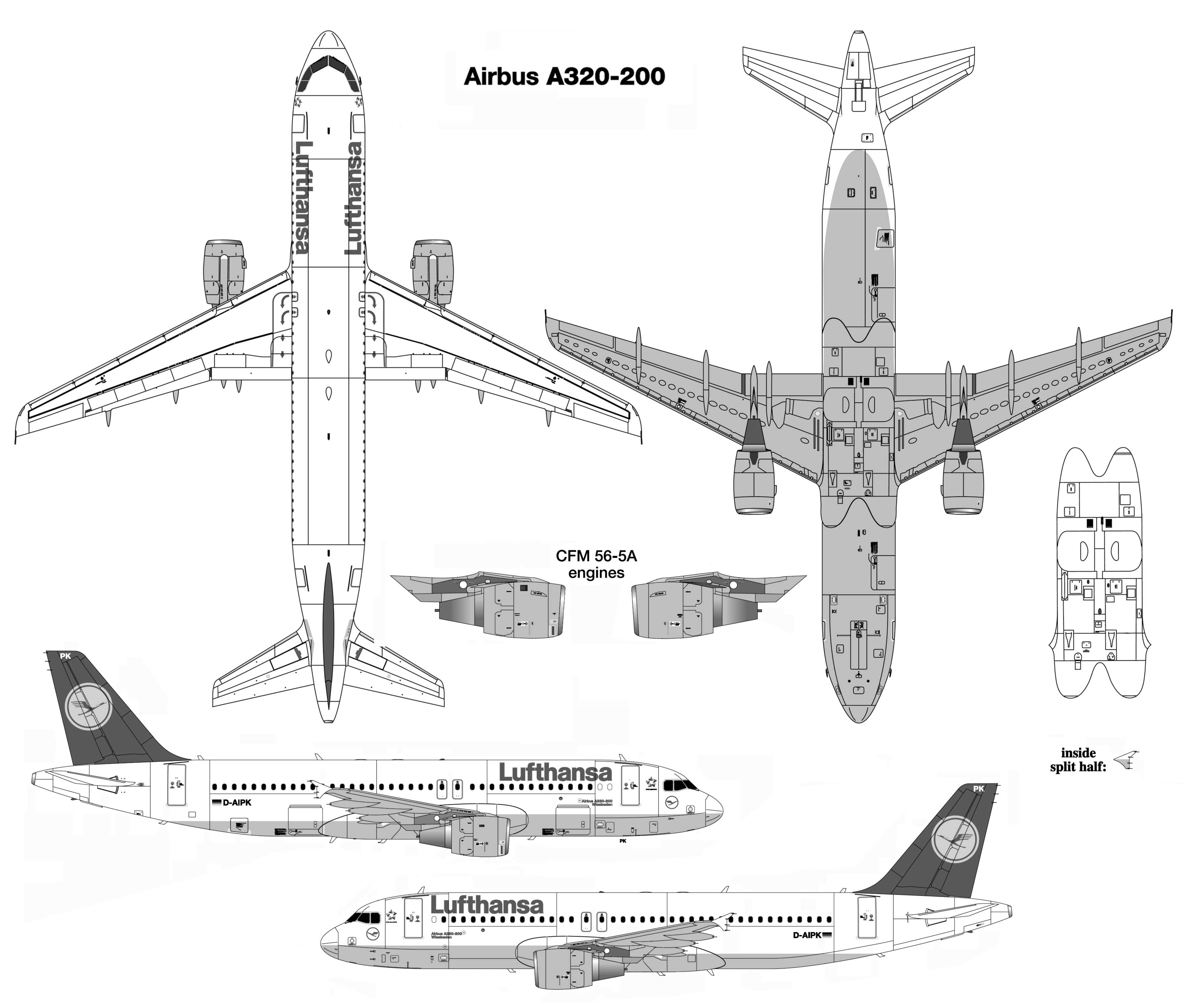
This is my reference image (notice how the spoilers cover the flaps' leading edge):

a320-200 blueprints

Here is the .blend file:

http://www.pasteall.org/blend/36159

$\endgroup$
1
  • $\begingroup$ Hey, just ran across this and thought you might want to take a look for the problem. blender.stackexchange.com/questions/38482/… Just wanted to let you know; I'm still watching out for easier ways. :-) $\endgroup$
    – Cyberchipz
    Commented Sep 16, 2015 at 1:20

3 Answers 3

6
$\begingroup$

The problem is, in your mesh model and as shown in the images, the mesh making up the wing tapers from the fat end to the narrow wing tip. This makes the lines appear, kind of, parallel but they are just straight lines with various angles at different x,y,z levels, so when you extrude, the extrusion stays at a right angle (normal) to the lines being extruded from; but, while the long(itudinal) edges are mostly parallel, the (latitudinal) edges of the flap or any other part of the wing change in the XY axis.

In other words each line making up the wing and flap have a similar vanishing points (are nearly parallel), to make the streamline wing, but they are not aligned to the extrusion point. So, it's not possible to extrude along the normal, and end up aligned with the flap or other points on the wing; but, you can edit the verts, or edges you extrude from the surface, to make them align.

Here's how I would do it. Read this first, I have put step by step instructions below this talk through.

While looking (top view) down on the plane, in vertex select mode, select the verts that represent the width of the spoiler you want to make, where you want to start the extrude. (With the instructions below, we're going to end up with single plane aligned the way you want).

Looking at the wing from the side view, extrude the verts at the approximate angle you wish toward the flaps (a combination of X & Y axis). This will give two edges at the angle you want (temporarily) above the Z axis.

You will now have two edges, two verts each; two are part the wing edge, and two at some height above the z-axis at an angle toward the flaps, but not yet what you want.

Go back to the top view. We're still in vertex select mode; but, we want, snap to vertex ON, and select vertex, (the magnet 'snap during transform' or use Shift + Tab, and 'type of element to snap to: vertex' (right next to the magnet, select vertex).

You will first need to select one of the two end verts of one of the two extruded edges, then press key G (grab), then degress of freedom for X & Y axis by Shift + Z [this says, freedom to move in X&Y but not Z axis.] This will allow you to retain your Z-axis (height of that vert above the wing or flap), but will allow you to snap to one of the verts that are part of the wing (or flap), without actually snapping to the wing (or flap)! So, you have grabbed, and set X & Y axis (not Z), now move to the correct vert, you may have to move your pointer around till you see it snap to the one you want. Once it has snapped to the vert you want, click to set it. Now, do the same for the other vert of the 2nd extruded edge.

Turn off snap to: (magnet)

Add a face in the usual manner, select the four verts of the extruded edge, and press F to make face. You can now edit as you wish.

Note: If you need to adjust the z axis, just select the two verts, press G > Z to only move them along the Z axis to adjust the angle.

Here are the steps and modified blend: http://www.pasteall.org/blend/36162

  1. Top view (ortho), (Vertex select mode) select two verts to extrude for spoiler.
  2. Side view (ortho), extrude in the general directions and angle you want.
  3. Turn on Snap to (magnet) and vertex in the bottom menu.
  4. Top view (ortho), G to grab one of the verts, Shift + Z (select X,Y axis)
  5. Move pointer to vert to snap to: may have to wiggle pointer around to get it to snap to the vert you want.
  6. Use LMB to set vert.
  7. Repeat steps 4-6 for other vert.
  8. Turn off Snap to (magnet)
  9. If you need to adjust angle
    • Top View (ortho), Shift + RMB the two verts
    • Side View (ortho)
    • G to grab, then Z to select Z axis.
    • Move up or down for correct angle.
    • Press LMB to set.
  10. Set face by selecting the four (4) verts of the spoiler, pressing F make face.

Of course, you'd have to remove some faces if you want to see through the wing that made the spoiler, and put in some machinery; but, that's another question.
$\endgroup$
5
  • $\begingroup$ Thank you for this incredibly detailed answer! But Im trying to model the spoilers out of the wing body, they should start on the tip of the body and cover a small lenght of the flaps. I've tried to use this method but with no luck yet ): $\endgroup$ Commented May 26, 2015 at 13:33
  • $\begingroup$ I extruded this from the wing body; and you can't just extrude, as I said, because extrusions have edges with are normal to each other and the wing. The wing is not drawn normal to other parts of the wing because it is not a square shape. So, you have to edit the extrusion to put it over the wing, and over the flaps. How long the extrusion is, how far it goes over the wing and the flaps. It's all about the verts you chose to align the end extrusion. The 2D view has perspective even in ortho, because we only see in 2D on the screen; but, it will be correct observed from all correct angles. $\endgroup$
    – Cyberchipz
    Commented May 27, 2015 at 14:51
  • $\begingroup$ I used the verts at the closest edge of the flap, you have to pick another vertex on the edge. The problem is that the alignment is to the z axis, looking down, just select verts on the sides of the flap further along the wing towards the flap tip. If a vert doesn't exist, you will have to either eyeball it, which will be tough, or your will have to make one on the flap, to ensure it's aligned right. As far as I know, there is no easier answer because of the wing shape. It is because the wing has yaw and pitch. $\endgroup$
    – Cyberchipz
    Commented May 27, 2015 at 15:00
  • $\begingroup$ The problem is in how the design was drawn, and the way extrude works. The wing in the image is not of the same design as in the blend. The answer provides a technique if the design has the data needed to extrude. Another way to get the perspective you want, if it doesn't exist in the design, Using the same technique, I would first overlay a rectangular 'mesh plane' onto the wing face by snapping the four vertices of the 'mesh plane' to the face of the wing; then pivot, and raise it to the correct angle. Simple extrusion would only work with modification of the way the wing is drawn. $\endgroup$
    – Cyberchipz
    Commented May 27, 2015 at 17:16
  • $\begingroup$ I pratically only have a top down ortho view of the wing, I'll attach it to the question later $\endgroup$ Commented May 27, 2015 at 22:14
1
$\begingroup$

This method would be completely different from the other answer. If you are willing to attach the flaps after you make them, you could draw them separately from the wing. In Blender, when you extrude, you can specify an axis of extrusion. If the line from which you want to extrude was aligned along the x,y or z plane, then you could extrude that line along one of the other two planes. Try these commands to make your first line, keeping in mind the number of segments you want.
you need a single vertex. To get this vertex:

  1. Add a mesh plane. Go into 'Top Ortho' view mode to see X & Y axes.
  2. Tab to edit mode.
  3. In the bottom menu, select snap to 'vertex'
  4. Select three vertices by Shift and click on each, or "C", and 'using scroll wheel to size circle' click to select each of 3 verts to remove. Wheel-click to remove a section if you accidentally select all. (My select button is my left, my release is my right mouse button). When done, release the circle by clicking the left mouse button (right in my case). You will now have 3 verts selected.
  5. 'X' & 'V' to delete 3 verts, you now have one vertex.
  6. Type 'Shift-C' to center the view, and place the cursor at the center.
  7. Select the only remaining vertex. Type 'Shift-S'(Snap) and "C" (Selection to Cursor) to place the vertex at the center of the three axes.
  8. To make a 5 segmented line, "E"xtrude "X" to constrain the extrude along the X axis, then click to create the extruded line. Repeat for each segment, making sure to select the X axis till done. You will now have a line of n segments along the 'X' axis.
  9. While still in edit mode, you can either select 'all' to select all the vertices, or select two, to select an edge.
  10. "E"xtrude "Y" to extrude constraining the extrude to the 'Y' axis only. Repeat for additional lines.
  11. You will now have your flaps.

You will still have to join them to the wing of the plane. Please post another question, as I'm restricting the answer to creating the flaps. Attaching them to the wing is another skill. You will need to orient them before joining them (CTRL-J). But, you just can't get away without having to orient the flaps. You will need to work in 3 dimensions to do this, and you will see that the process needed to do this has similarities with the first answer. Blender has to be specifically told which way to extrude, and draw lines. It would be nice it we could constrain the extrude at a specific angle, but you'd still need to figure out what that angle is.

$\endgroup$
1
$\begingroup$

Another method would be to use "Local" and "Global" axes. I believe this is what you want. For each part of the plane, you will have several Local Axes groups, this depends on what is aligned with what. You will sill need to make your orignal edges and such aligned globally, but, before you rotate them to align to a new orientation or angle, you will need to switch to local mode.

Make all your angle changes in local mode, like the angle that the wing sweeps back. Each line would have it's own orientation from along the global X,Y, & Z axis. If you're new to this, you'll have to make a line, and play with it some to see how this works.

By changing the orientation in local mode. The object or lines done locally will have two orientations. Global will be aligned with the X-Y & Z axis that is normal to Blender. (I don't think these can be changed.) However if you switch to Local, then Rotate or Translate, these now have their own axes. So, a line can be at 45° toward the y axis globally, and extruded along, these global axis, or they can be extruded along the local axis which has the 45° from global as the x axis. To extrude using local axes. You would 'E'xtrude "XX" or "YY" or "ZZ". Note, if you rotated the lines in Global mode, and didn't switch to "Local" before rotating it, all axes will be aligned to global still. Local mode transforms the axis, not the object when doing rotations.

Hope this helps.

$\endgroup$
0

You must log in to answer this question.

Not the answer you're looking for? Browse other questions tagged .