3
$\begingroup$

enter image description hereWhat i did here is simple: 1: Create a cylinder, shade smooth, then auto smooth 30° 2: Insert two loop cuts in one of its side faces

After that i switch to object mode and i got a shading problem, a thick line clearly deforms the cylinder. 1: I want to know why this happens 2: Is there any way to fix it

thank you very much for you reading)

$\endgroup$
1
  • $\begingroup$ Basically, this is happening because you've added faces in a non-uniform way, and shade smooth is trying to make your object appear perfectly smooth given that geometry. $\endgroup$ Commented Jun 8, 2022 at 13:53

2 Answers 2

2
$\begingroup$

Faces 2, 3 and 4 make a flat surface. As you've shaded smooth, Blender creates a gradient between face 1 and 2 and between face 4 and 5, but not between the right of face 2 and face 3, nor between face 3 and the left of face 4, therefore face 3 has an homogeneous grey color and it visually creates this kind of stripe you show.
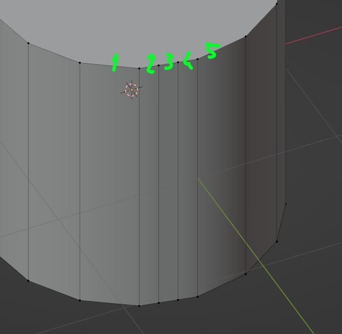
enter image description here

To fix it you can try the Data Transfer modifier, which will change the split normals of your object (split normals = normals that determine the shading):

  • Create another cylinder (Cylinder 2) at the exact same location as your original cylinder (Cylinder 1), give Cylinder 2 a Subdivision Surface modifier in order to make it round. Make it invisible (here I just display its wireframe).
  • Select Cylinder 1, select the faces 2, 3 and 4 and asign them to a vertex group.
  • Give the Data Transfer modifier to Cylinder 1, choose Cylinder 2 as Source, Vertex Group > select the vertex group you've just created, click on Custom Normals, and select Mapping > Projected Face Interpolated. Result (you can apply the modifier if you're glad):
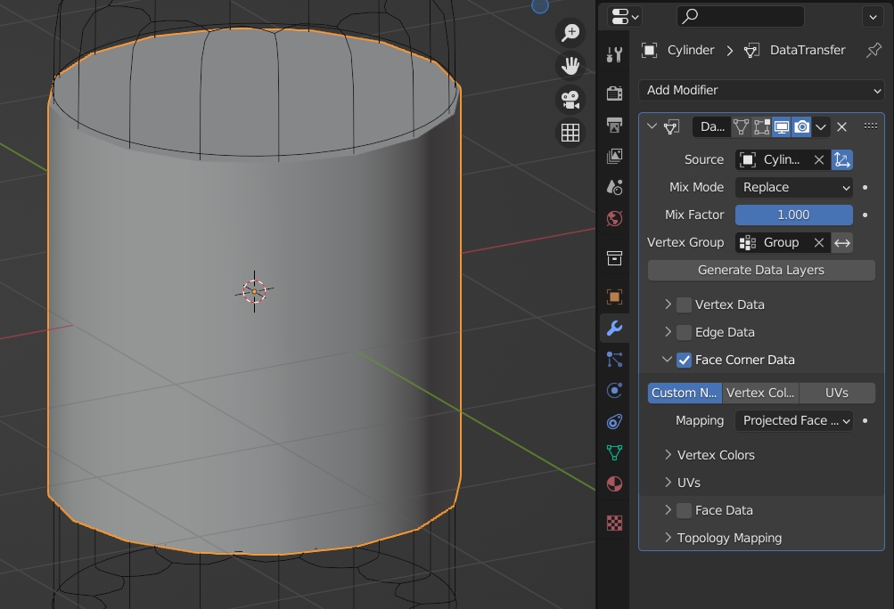
enter image description here

$\endgroup$
6
  • $\begingroup$ Amazing explanation, is there any solution to correct this problem while keeping those two loop cuts? $\endgroup$
    – Ninja
    Commented Jun 8, 2022 at 14:32
  • 1
    $\begingroup$ You need to move your 2 new edges, for example you can create a cylinder with a higher number of vertices at the exact same position and use it as a Target of a Shrinkwrap modifier that you give to your first cylinder, so that the edges stick to a circular shape $\endgroup$
    – moonboots
    Commented Jun 8, 2022 at 14:35
  • $\begingroup$ or simply move face 3 a bit along its normal $\endgroup$
    – moonboots
    Commented Jun 8, 2022 at 14:46
  • $\begingroup$ I tried it but it gets worst, any other solution? $\endgroup$
    – Ninja
    Commented Jun 11, 2022 at 8:00
  • $\begingroup$ @Ninja you can try the Data Transfer modifier, I'm going to edit my answer $\endgroup$
    – moonboots
    Commented Jun 11, 2022 at 8:16
0
$\begingroup$

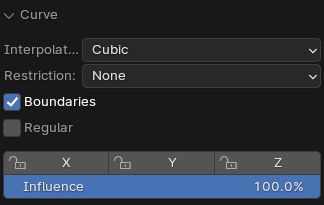
Choose at least three nearby edge loops and use Curve in LoopTools add-on, with the following settings.

enter image description here

Sometimes it works very glitchy so try turning Boundaries and Regular On/Off few times or change settings to other and back.

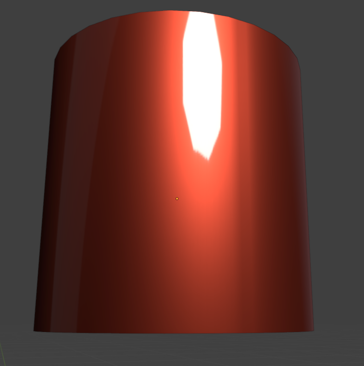
enter image description here

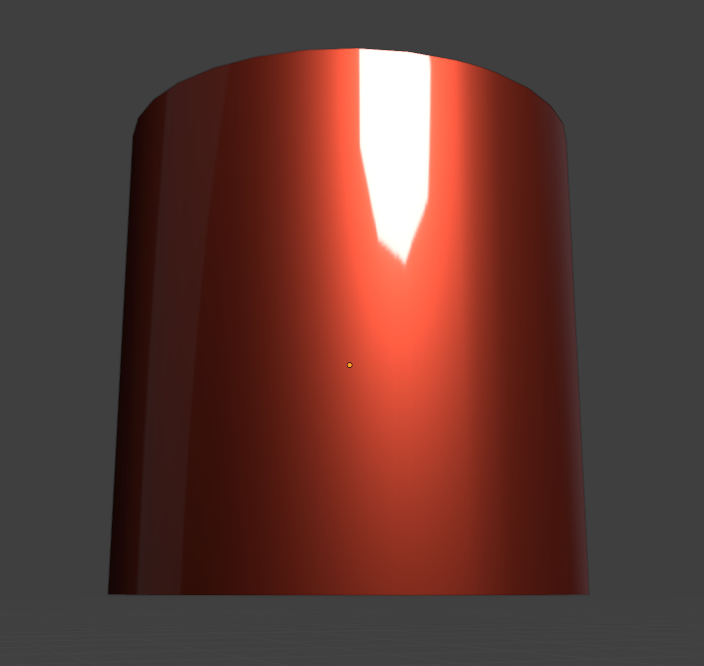
Blender might still show little warping there but I think its just due to the fact that there are more edges so you cant make it any better as new verts follow circle curve so they have perfect position.

enter image description here

enter image description here

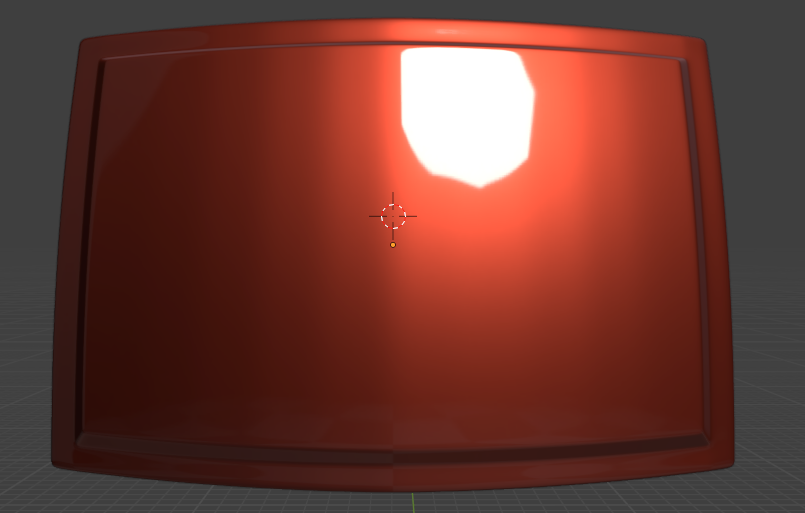
My model before/after

enter image description here

$\endgroup$

You must log in to answer this question.

Not the answer you're looking for? Browse other questions tagged .