6
$\begingroup$

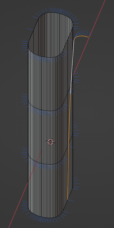
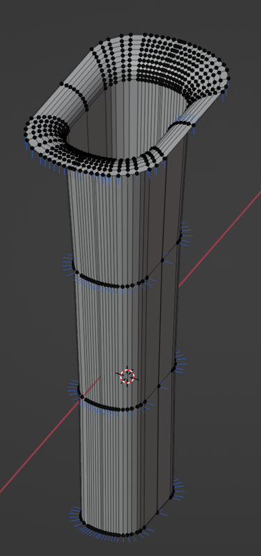
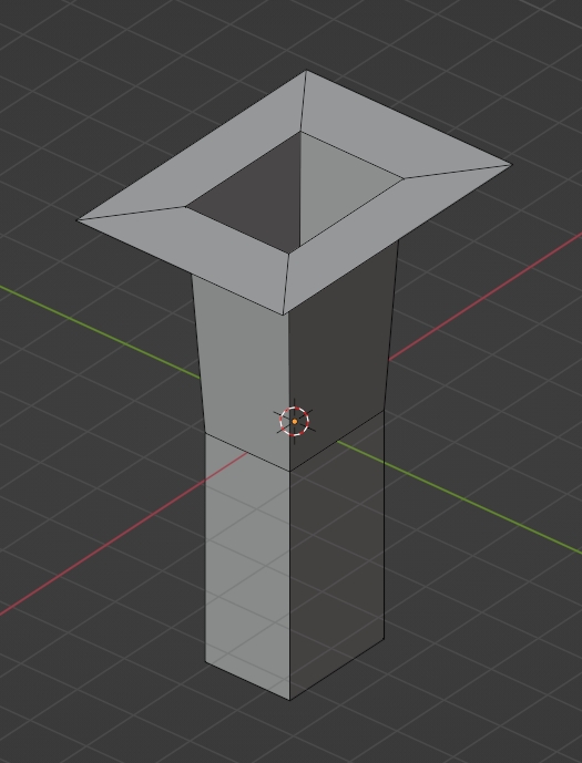
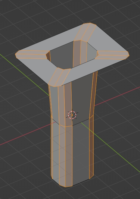
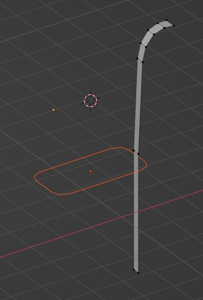
I have a (at the moment extruded) profile and a "rail" (selected edges in the first image). I want the extruded profile to follow the curvature of the rail (a bit like in the second image).

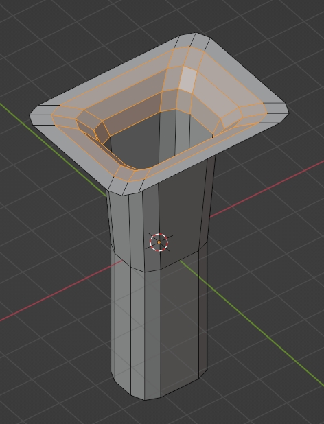
In the second image I used scale+vertex snapping to give an idea of the desired end result (but here the result is of course not regular (as it only scales from a single reference point in the middle of the profile, so the further away vertices will be scaled too much)).

The obvious solutions to me would have been to either using the shrink/fatten tool (Alt + S) for each profile loop, but sadly it seems there isn't any support for snapping with it.

The other solution I thought of (and thought it would be easy) was to convert these two into curves and use bevel and taper ... but man, that is very unintuitive and even after watching quite some tutorials I did not get it to work).

How can I best achieve this?

Image 1

Image 2

$\endgroup$

2 Answers 2

8
$\begingroup$

As you said, converting it to curves and using one as the profile works a little counter-intuitive. Here's how you do it (sorry, my model has a slightly different shape):

Just take the bottom edge of your object and convert it to a curve: Object > Convert > Curve, do the same with the vertical profile.

Select the bottom edge and go to the Curve Properties. Under Geometry > Bevel switch to Object and there you choose the vertical profile.

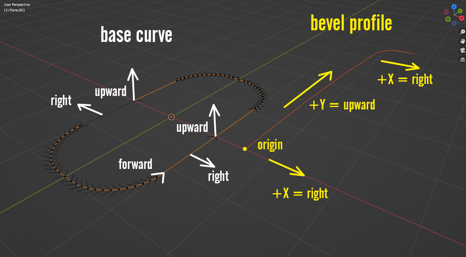
Now, to understand how this works: the bevel profile will be following the curve with its origin point. This means, you have to set the origin of the bevel profile on the vertex at the bottom. The orientation of the bevel profile (when the rotation is applied and all set to 0°) is like this: vertices in positive X direction point to the right of the base curve's forward direction. Vertices in positive Y direction are pointing in upward direction of the base curve. So the curves should be setup like this:

bevel setup

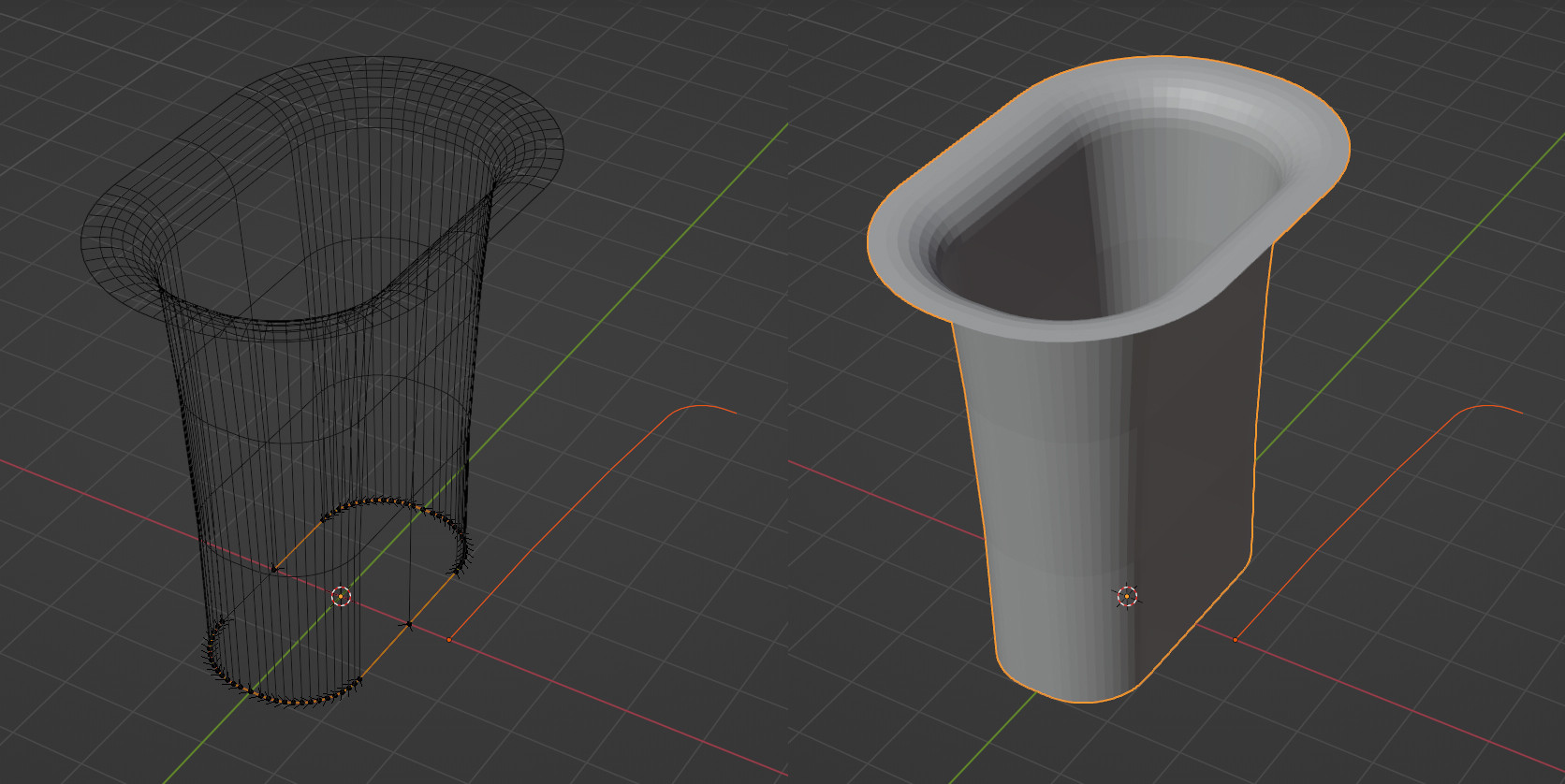
The result looks like this:

bevel result

$\endgroup$
6
  • $\begingroup$ @Gordon Brinkmann This is a very good explanation (the clue with the origin is especially helpful) and it should work... but somehow i get this as a result: de.catbox.moe/p3tol0.png ... at the base it has the right size but at the top it is much much much to wide and overall it is much much much too high. (All transforms were applied before) $\endgroup$
    – CoD
    Commented Apr 7, 2022 at 17:13
  • $\begingroup$ @GordonBrinkmann I need to scale the profile down by 0.001 to get the right result ... not sure why. (Does it have to do with unit scale beeing 0.001 and mm? But why do i not need to scale down the curve also then ... i am confused). Well, at least now i know how to do it, thx. $\endgroup$
    – CoD
    Commented Apr 7, 2022 at 17:19
  • $\begingroup$ Pardon, I missed that! $\endgroup$
    – Nathan
    Commented Apr 7, 2022 at 17:35
  • $\begingroup$ @Nathan Nevermind :) $\endgroup$ Commented Apr 7, 2022 at 18:12
  • $\begingroup$ @CoD This sounds a little strange when all transforms were applied... The problem is, my solution is built with my own models, whatever there might be in yours going wrong is not recreated this way. Maybe you could upload your file so I can investigate it further? Maybe there is a certain reason it's not working as expected. What I don't understand in your picture with the result, why is the bottom such a pinpoint, where is the original rounded rectangular shape? For the scaling issues: very often this is caused by the different scaling and number formats in different softwares. $\endgroup$ Commented Apr 7, 2022 at 18:21
1
$\begingroup$

In my opinion it would be easier to redo it properly from scratch, plus it's better to use less vertices and then subdivide with a Subdivision Surface modifier:

  • Create this shape:

enter image description here

  • Bevel these edges:

enter image description here

  • At last bevel these ones:

enter image description here

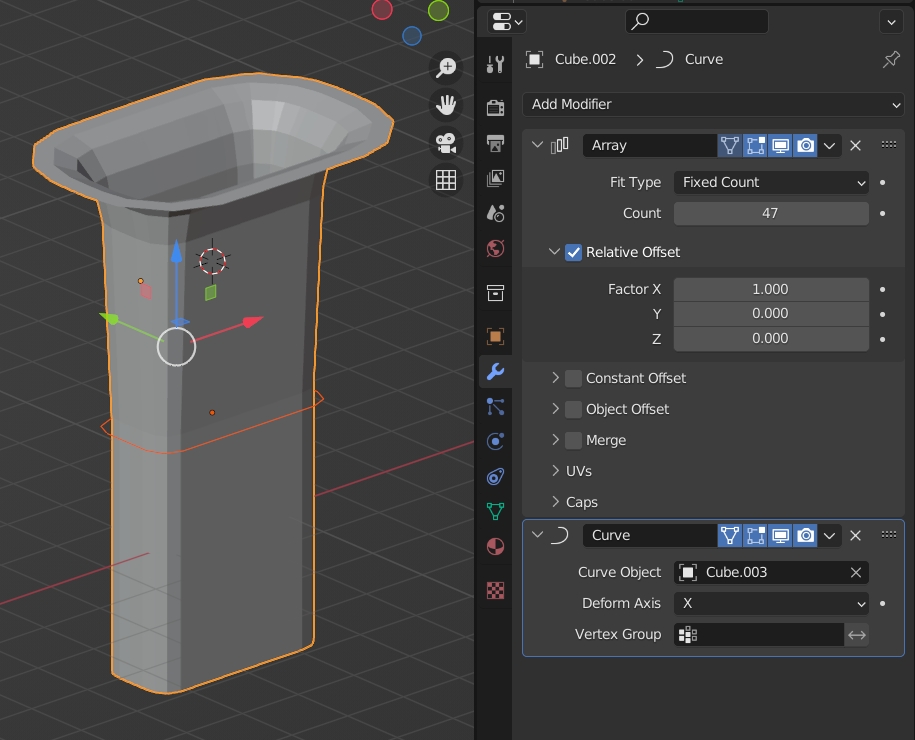
Another way would be to extrude your profile a bit and give it an Array modifier to repeat it and a Curve modifier so that it rotate around your square:

enter image description here

enter image description here

$\endgroup$
3
  • $\begingroup$ The shapes are done in a CAD software using exact measurements and constraints etc. and imported to Blender (as 3D capability of the CAD software ... is not very nice for several reasons). It is also only one of much more shapes with different dimensions. So redoing it in Blender is more or less out of questions. $\endgroup$
    – CoD
    Commented Apr 7, 2022 at 16:14
  • $\begingroup$ oh ok but for the second solution I cite you don't need to redo it, you just need to convert the vertical curve into mesh $\endgroup$
    – moonboots
    Commented Apr 7, 2022 at 16:18
  • $\begingroup$ That almost works. Problem is, that the width of the segments is wrong (same width for everything, while in the end result they are supposed to be the same width as the segments of the profile). $\endgroup$
    – CoD
    Commented Apr 7, 2022 at 16:50

You must log in to answer this question.

Not the answer you're looking for? Browse other questions tagged .