10
$\begingroup$

I'm trying to make a procedural staircase using an array and solidify modifier. I created two planes (a rise and a run) like this: Base Geometry for Individual Stair
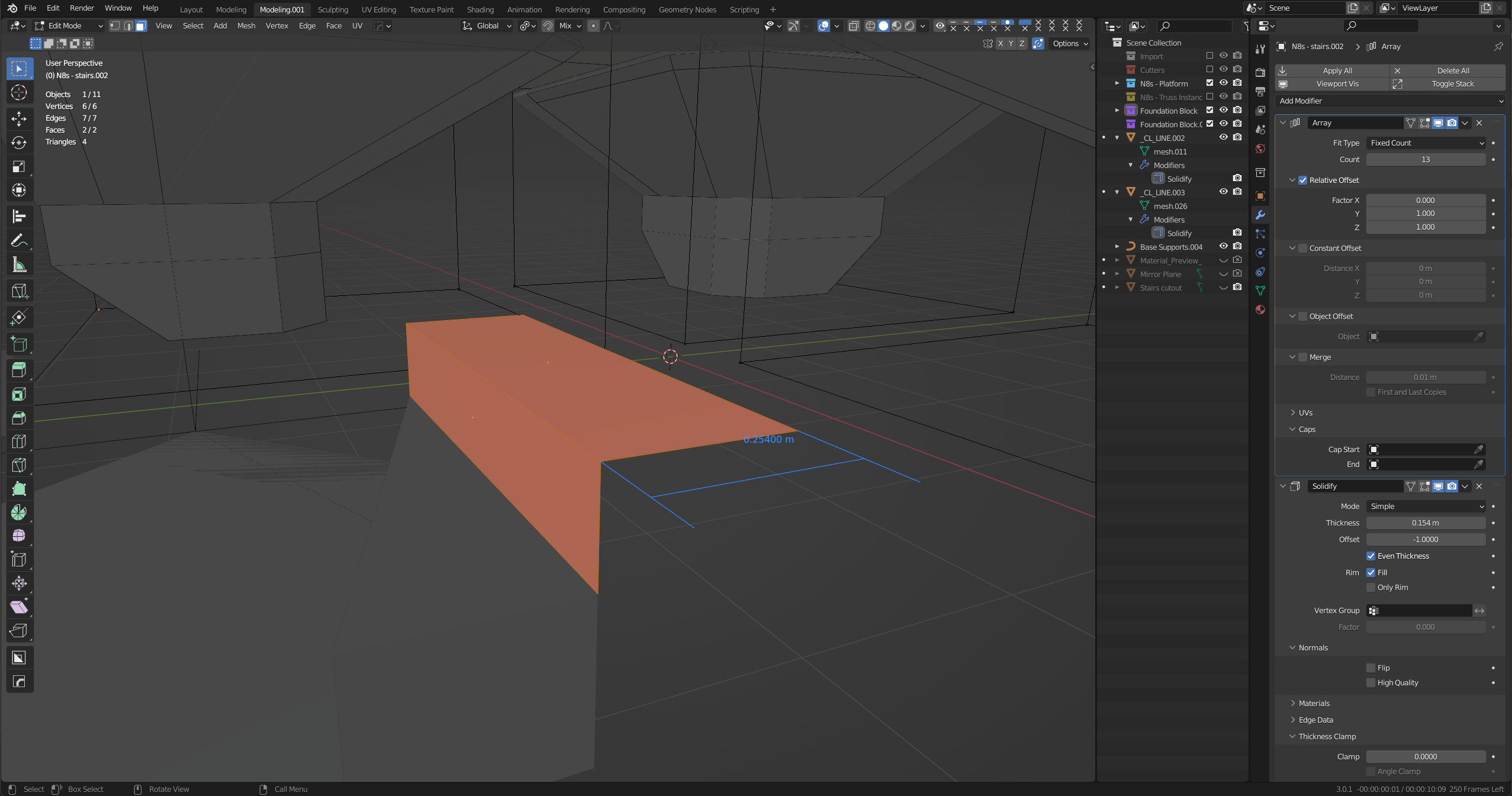
Then apply the array with a relative offset of 1 in the Y and Z directions and solidify everything into a staircase that looks like this: Modifiers Applied to Starting Planes
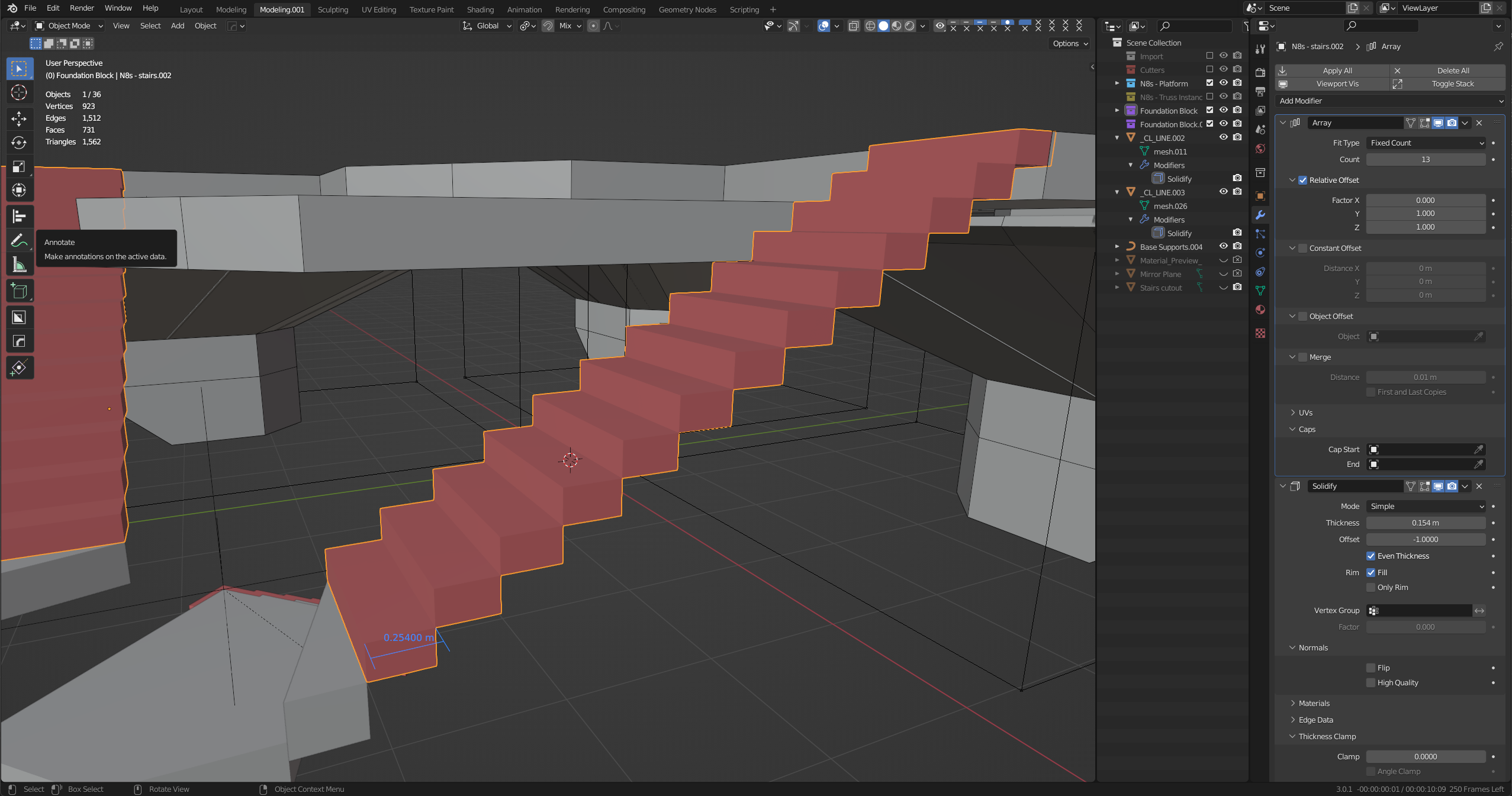
I would like to be able to generate a watertight mesh after applying the modifiers with the underside of the staircase being one single face (instead of the zigzag I've found in every other tutorial). I may be going about this entirely wrong as I think like a Sketchup user but here is what I'm trying to achieve: Intended Result
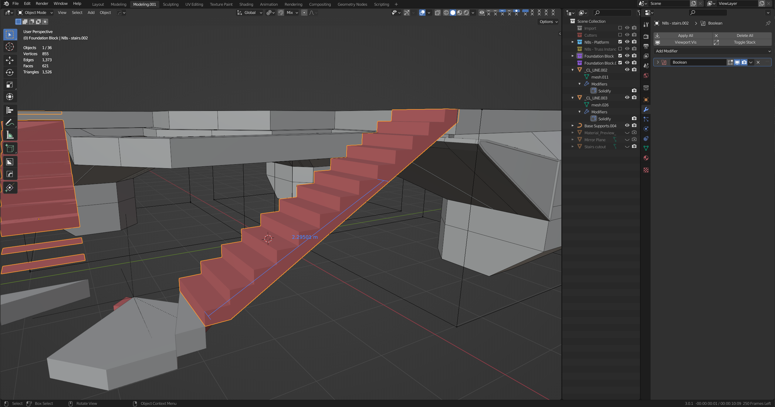
Is there a way to do this non-destructively where the rise and run, stair count, and flat bottom can all be controlled parametrically and independent of each other?

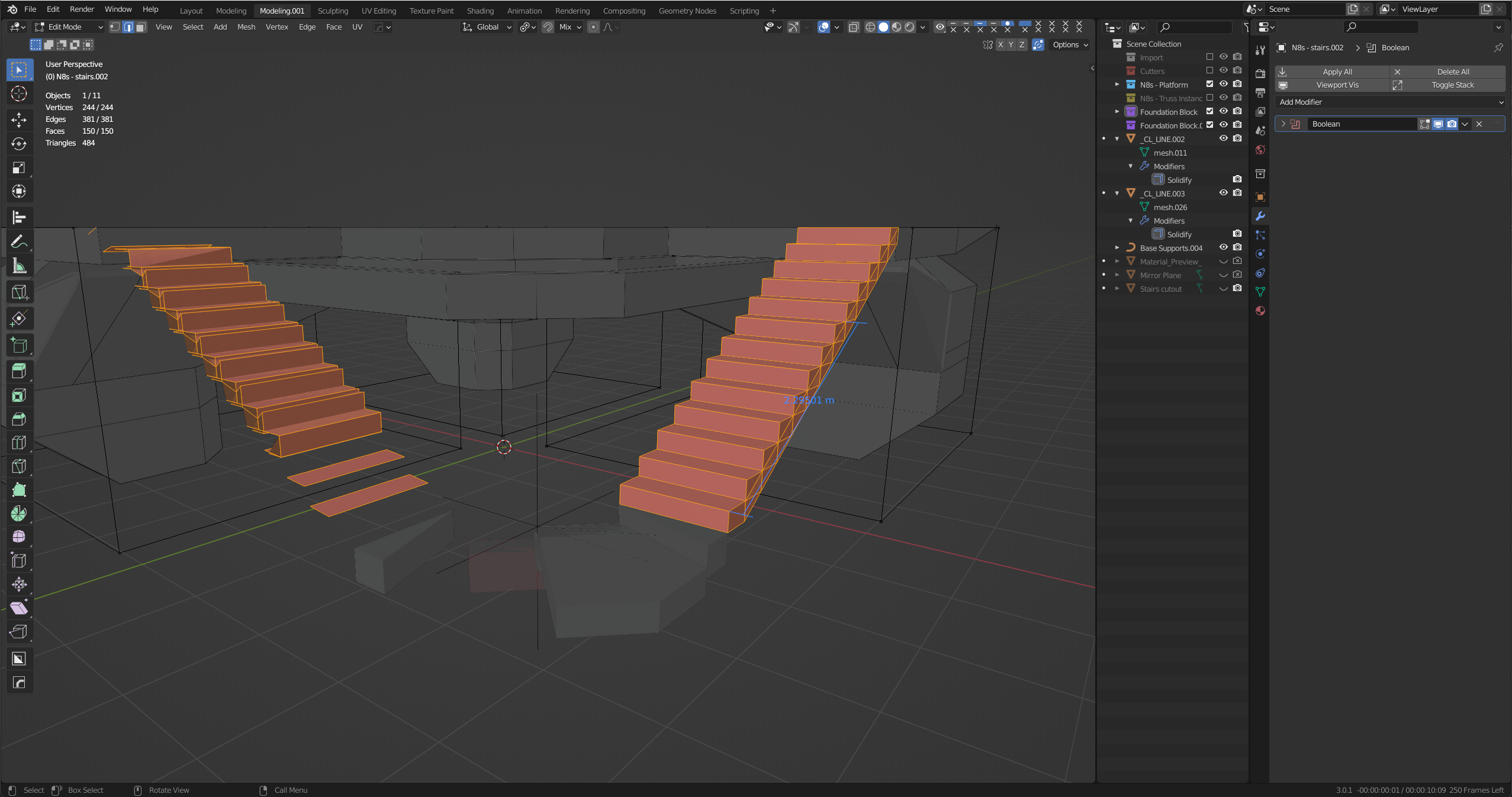
I had to apply the modifiers and still couldn't come up with a clean mesh for the example image above. I still couldn't come up with a clean topology, and it broke my mirrored staircase on the other side: Failed Attempt
$\endgroup$
4
  • 3
    $\begingroup$ Hi :). Give it some time and @Chris will bring his geometry nodes and build your whole house :)) $\endgroup$ Commented Mar 27, 2022 at 8:40
  • $\begingroup$ love you Jachym!!!!! :D $\endgroup$
    – Chris
    Commented Mar 27, 2022 at 9:39
  • 1
    $\begingroup$ @Jachym not enough time, at that, for slowcoaches like me to slot in an answer! $\endgroup$
    – Robin Betts
    Commented Mar 27, 2022 at 11:02
  • $\begingroup$ @ Robin Betts, you can still give the Python answer $\endgroup$
    – moonboots
    Commented Mar 27, 2022 at 11:26

3 Answers 3

8
$\begingroup$

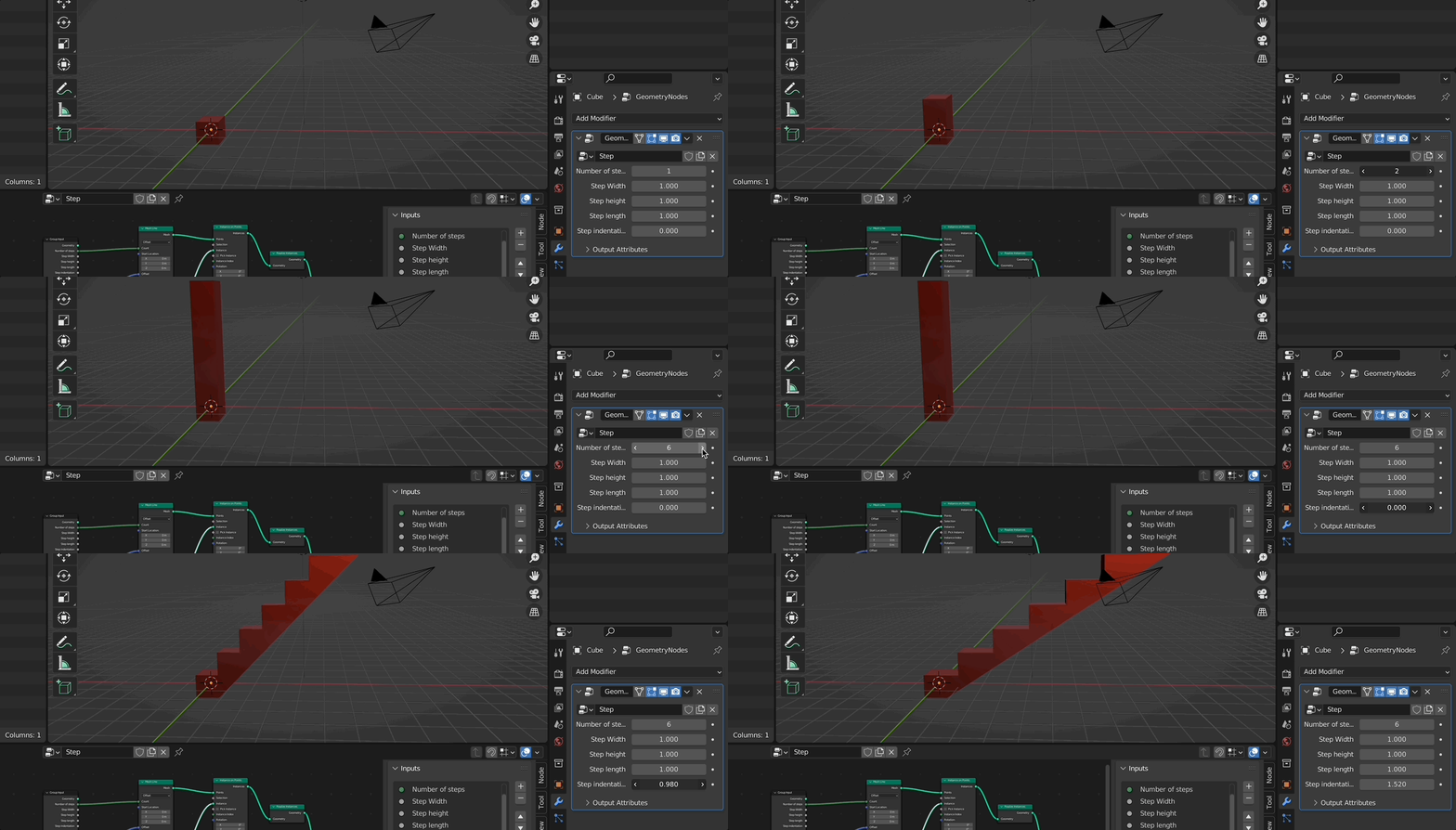
Here you are:

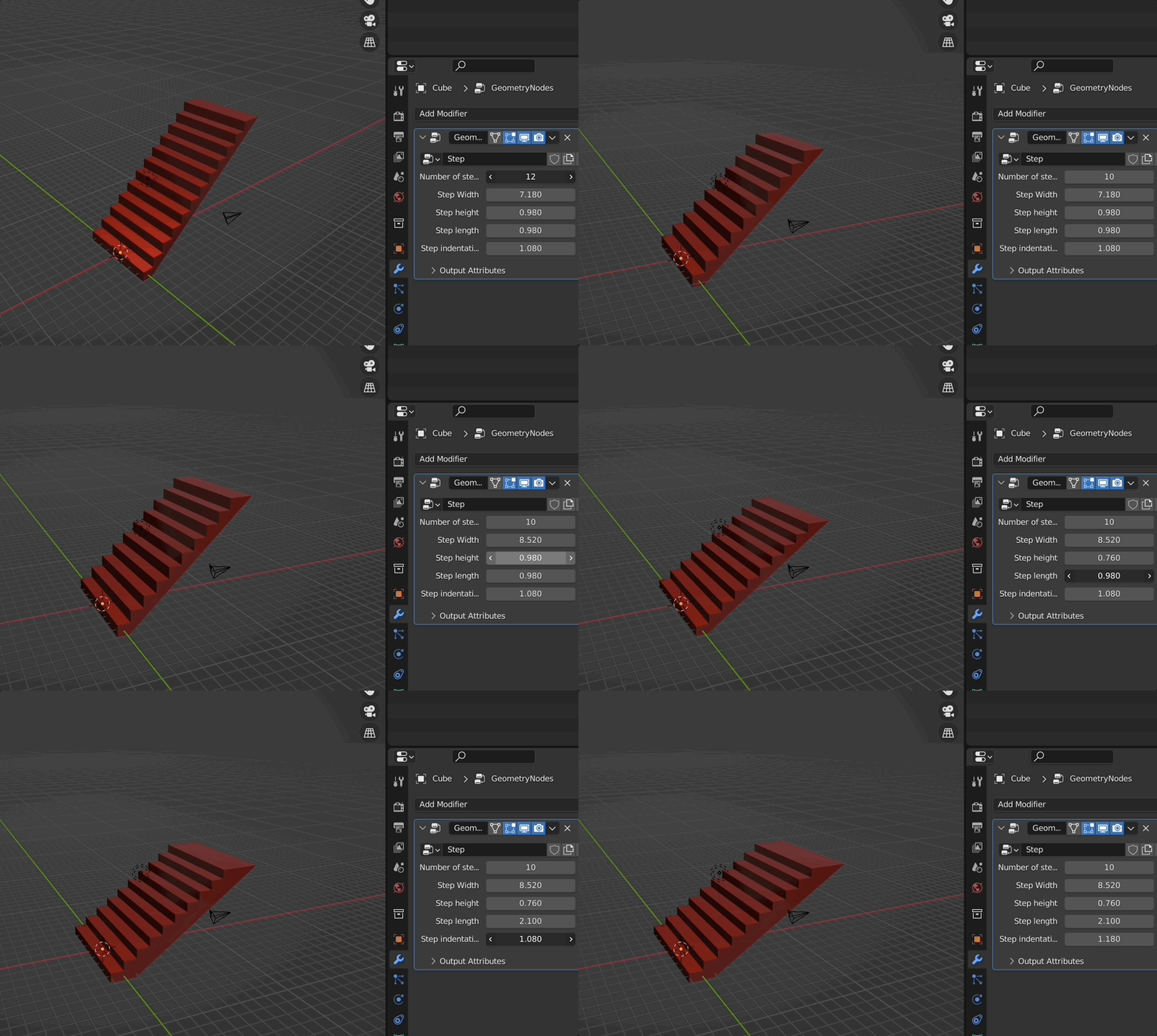
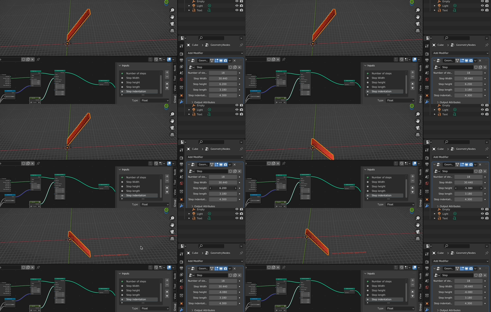
result:

enter image description here

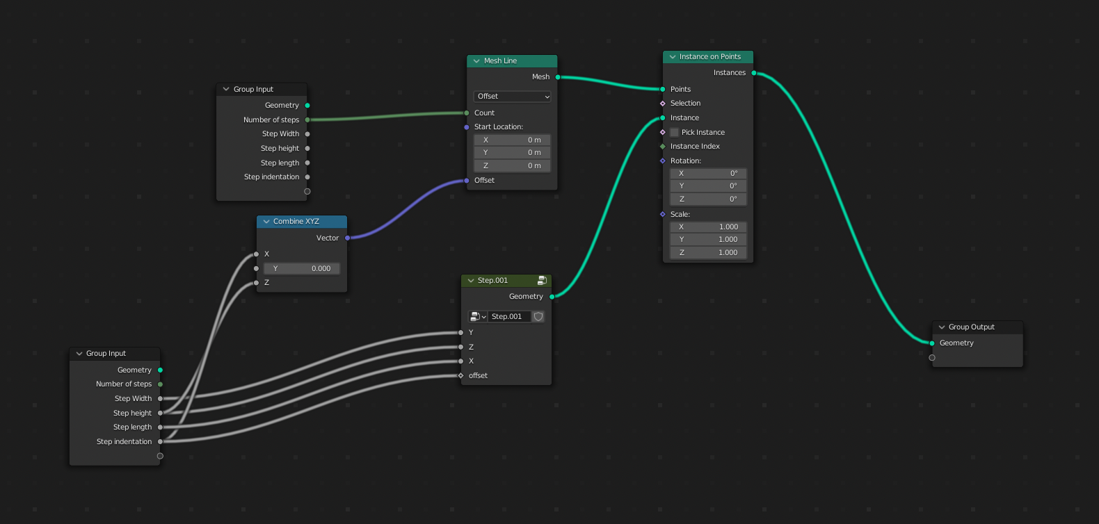
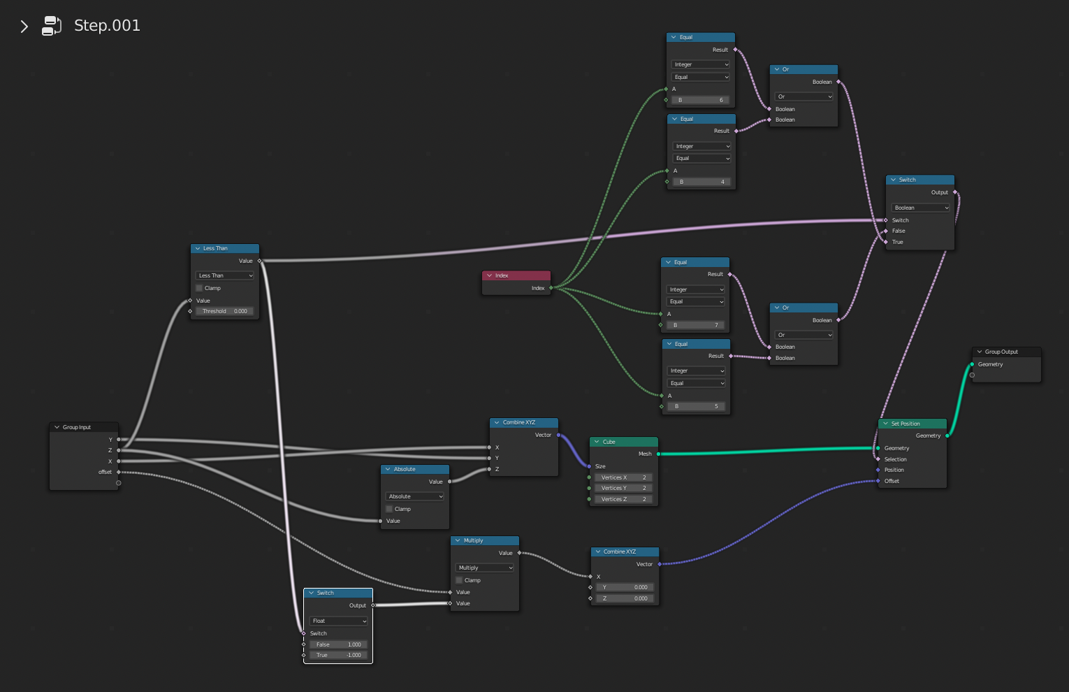
node setup:

enter image description here

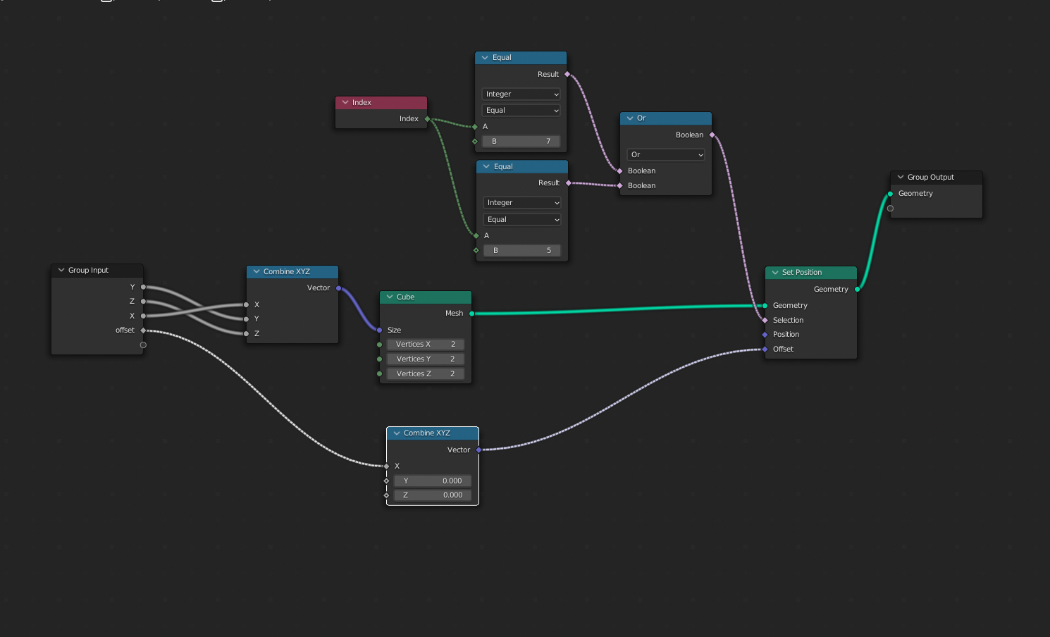
enter image description here

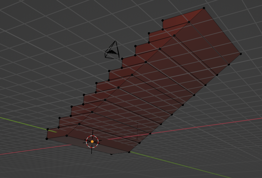
if you add a realize instance node before the output and apply it, you won't get one single face on the downside (sorry for that), but a pretty clean topology:

enter image description here

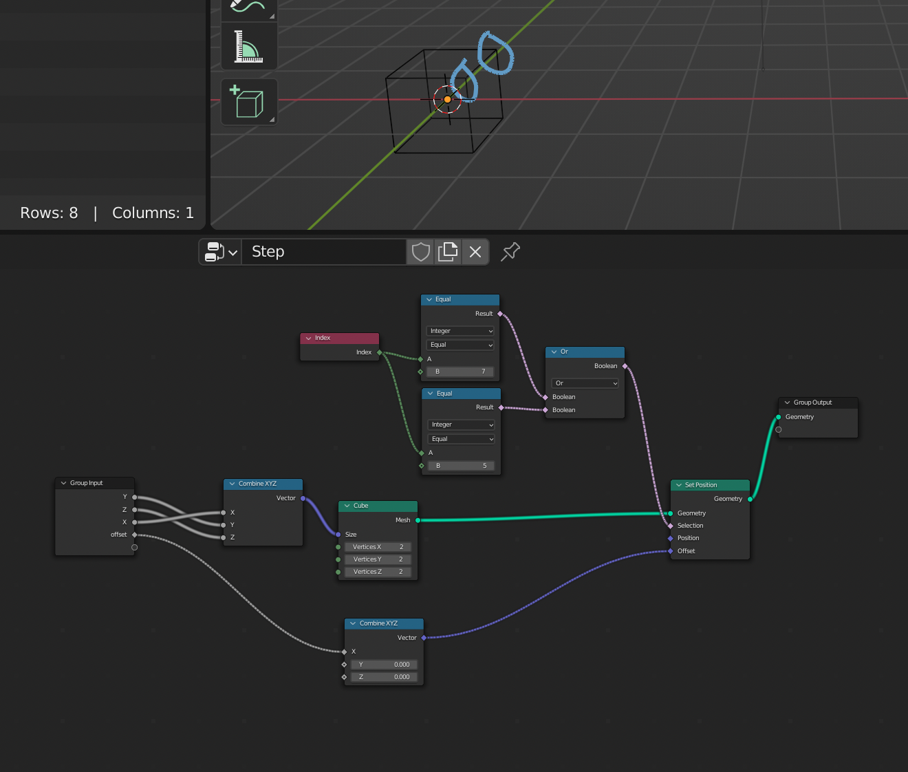
The step node just creates this:

enter image description here

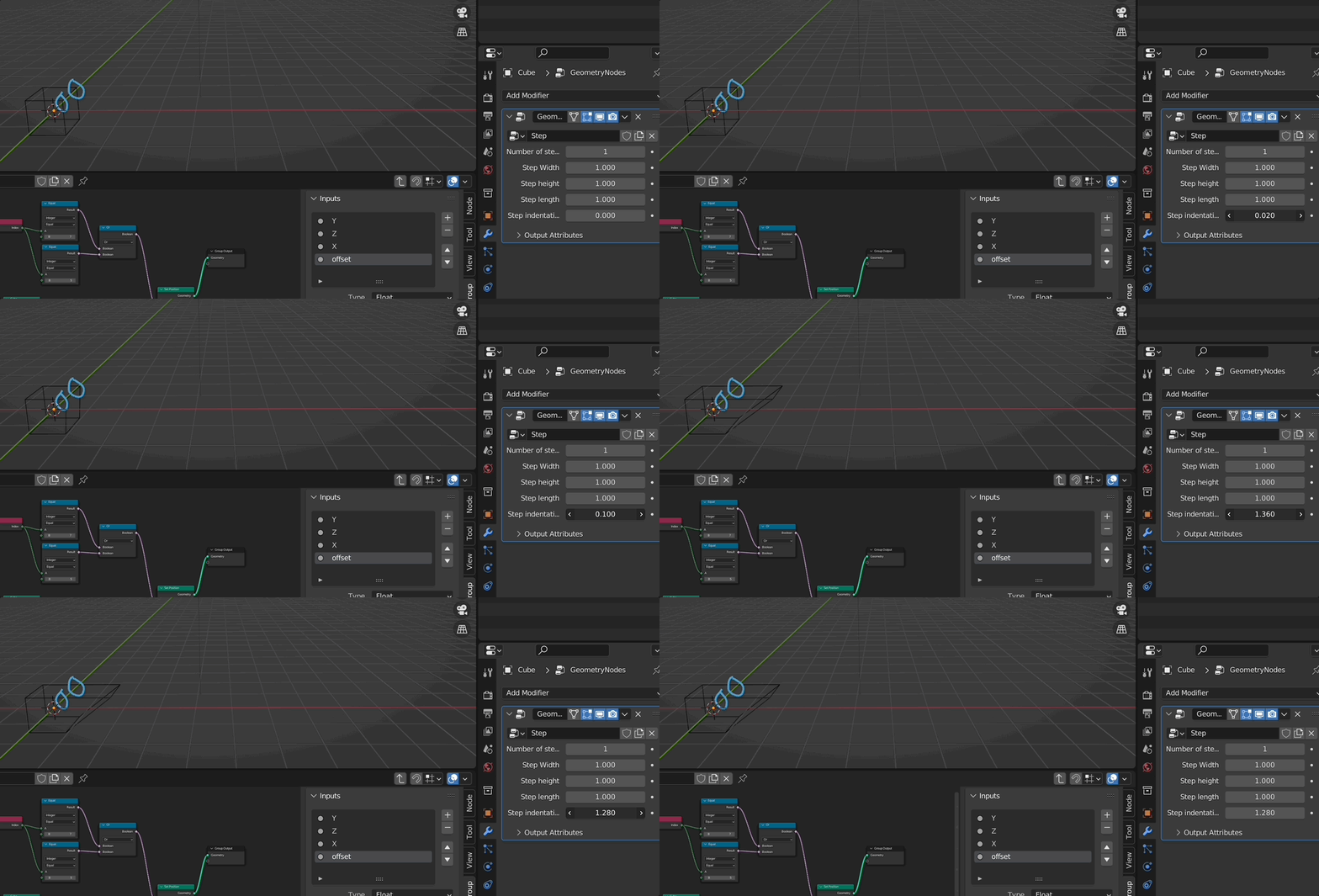
a box and the two vertices will be just pushed on the x axis.

enter image description here

the mesh line instances the steps in z direction. With the indentation value i push the vertices and at the same time move the instances on the x axis so that it fits.

enter image description here

maybe you are asking: is this all it can do?

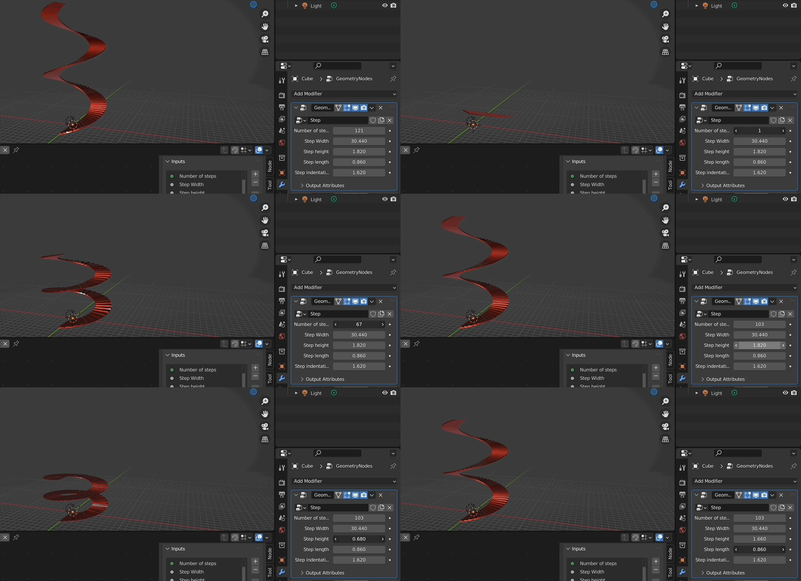
well...no...you can add e.g. a simple deform modifier, and you get this:

enter image description here

if you change the step node to this:

enter image description here

you can build stairs for your basement:

enter image description here

so with negative height you now get downstairs :D

$\endgroup$
8
  • 2
    $\begingroup$ ok you've made a stairs that goes up but are you able to make a stairs that goes down? I need one for my basement $\endgroup$
    – moonboots
    Commented Mar 27, 2022 at 10:17
  • 2
    $\begingroup$ @moonboots: challenge accepted! $\endgroup$
    – Chris
    Commented Mar 27, 2022 at 10:40
  • 2
    $\begingroup$ answer updated!! :D $\endgroup$
    – Chris
    Commented Mar 27, 2022 at 10:44
  • 1
    $\begingroup$ @Robin Betts, he is, at first he wanted to model an escalator $\endgroup$
    – moonboots
    Commented Mar 27, 2022 at 11:06
  • 1
    $\begingroup$ Beautiful, simple and robust; you are incredible my friend. This was my first question thanks for being a great community y'all! $\endgroup$ Commented Apr 4, 2022 at 8:50
11
$\begingroup$

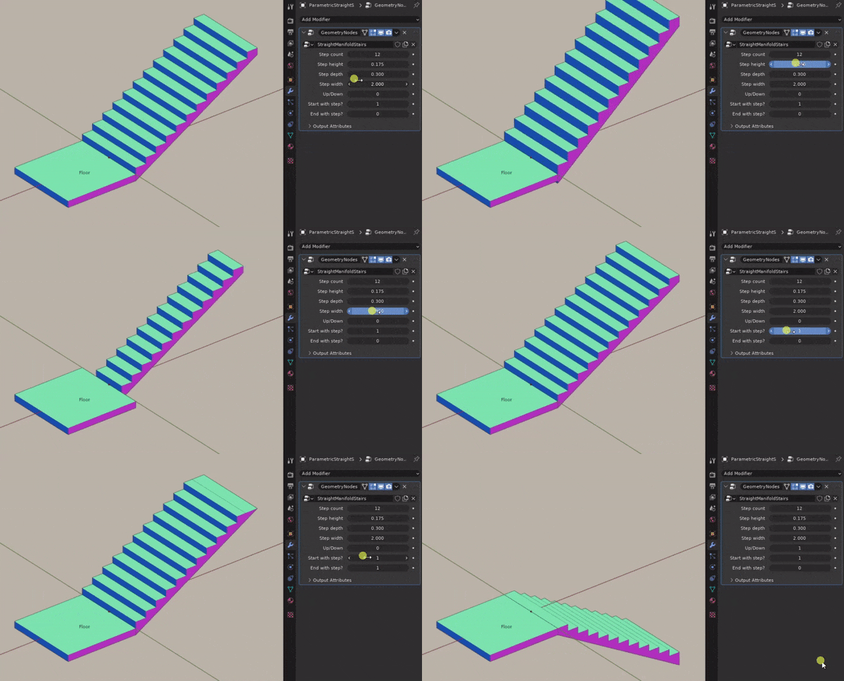
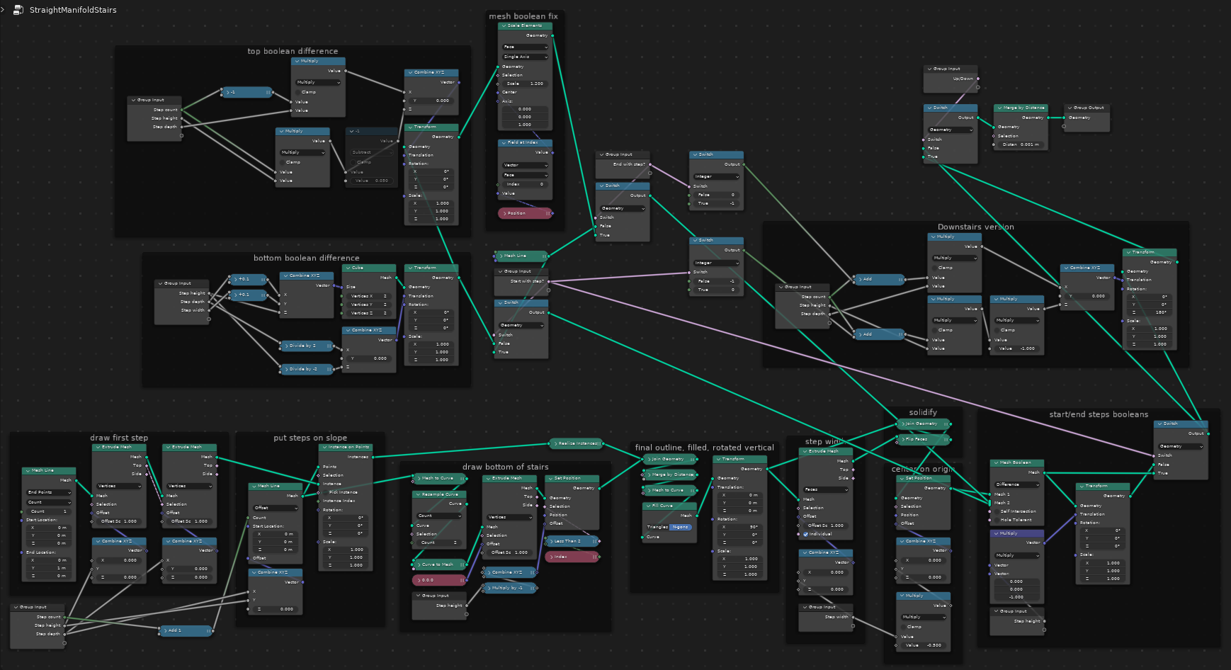
It seems I'm a bit late, but here's my Geometry Nodes entry with all your criteria satisfied, including optional start/end steps and perfectly manifold geometry:

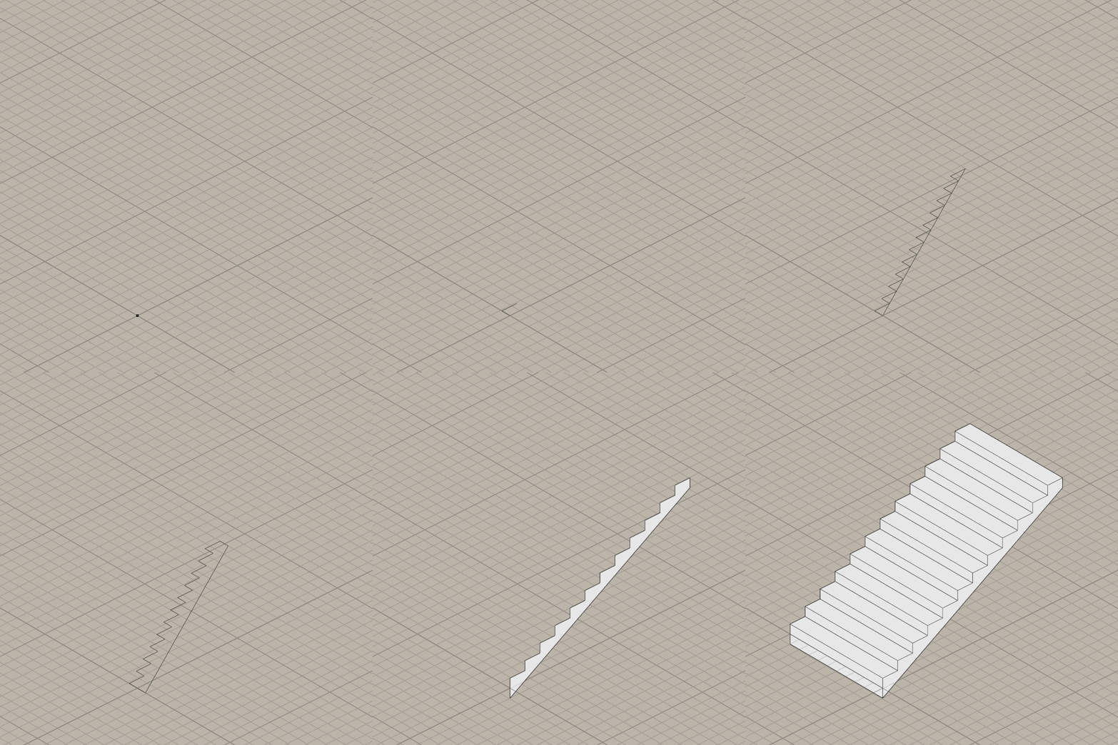
To get a manifold geometry I had to forgo using steps as instances and tried drawing the side section of the whole staircase edge by edge, and extruded the finished profile in one go instead:

enter image description here

enter image description here

$\endgroup$
1
  • 1
    $\begingroup$ That’s great! +1 $\endgroup$
    – Chris
    Commented Mar 27, 2022 at 17:36
4
$\begingroup$

Here's a non-node approach.
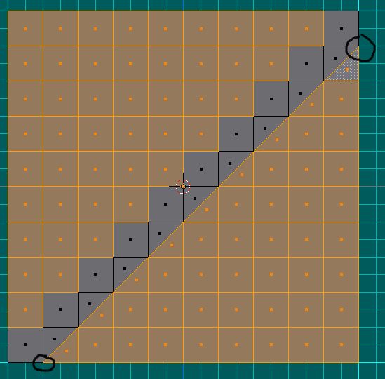
Create a subdivided plane as shown below
enter image description here

First join, with J, the verts cirlced then select, with B to make it faster, faces as shown

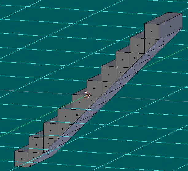
Remove the selected faces and Y-extrude

enter image description here

$\endgroup$
1
  • $\begingroup$ i just wonder for the upvotes here if the OP ask for a procedural (non destructive) solution....but yeah.... $\endgroup$
    – Chris
    Commented Mar 27, 2022 at 10:46

You must log in to answer this question.

Not the answer you're looking for? Browse other questions tagged .