0
$\begingroup$

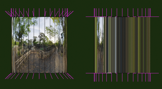
I am creating a character for didatic reason, and when I started to work with the material, it was stretched between where I had edge loop.

The issue is easily reproduced using a cylinder, with a default Principled BSDF shader, where Mettalic is set to 1 and Roughness is set to 0(the issue happens with any values between, but it is very notible with these values set this way).

Some important points:
The top and the bottom of the cylinder are not distorted
The UV mapping has not been streched
If I dissolve the upper edge loop(the one highlighted in the image for example) the stretching stars in the next one below.
The circles formed by the edge loop have the same radius
It seems to be a problem that I have in EEVEE and Cycles.
I can notice that an edge loop alone already cause some distortion on the reflection.

Is it possible to have edge loops without causing these distortions?

enter image description here

Solution: What happens I had misleading expectations, the above reflection is not real, but the result checking the "Auto Smooth" option made it much more realistic.

$\endgroup$
2
  • $\begingroup$ UV unwrap everything. $\endgroup$ Commented May 31, 2020 at 8:57
  • $\begingroup$ I have unwrapped it, but it made no difference, and I could not find any problem with the UV, as I mentioned it is not even stretched. $\endgroup$ Commented May 31, 2020 at 21:21

2 Answers 2

4
$\begingroup$

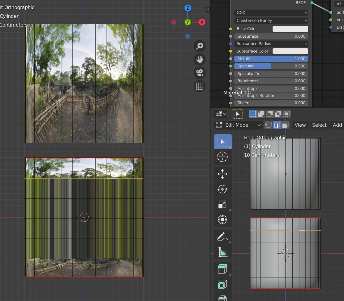
The reason for the difference is the top-to-bottom interpolation of normals, inside the rectangular faces. This illustration shows 2 standard cylinders. They are both shaded smooth, but the one on the right has Autosmooth switched on.

enter image description here

When smooth-shaded,the normal at some shading-point inside a polygonal face is an interpolation of the vertex-normals at its corners. Those, in turn, are a (sometimes weighted) average of the normals of the whole-faces which the vertices help to define.

As you can see on the left, in pure smooth shading, because of the top and bottom faces, those vertex-normals have a Z component, looking up and down. The interpolation between these gives the geometrically cylindrical surface a somewhat spherical field of interpolated normals. Strictly speaking,this actually produces the inaccurate reflection.

On the right, switching on Autosmooth introduces the influence of per face-vertex normals. Autosmooth sets a face-angle threshold for interpolation. Below the threshold, faces are interpolated, above it they are split. The top and bottom face-normals no longer influence the radial normals, which are then aligned to the geometry. In an orthographic view, like this one, the cylinder reflects only its own height in the environment. In perspective, the reflection is more like a real cylinder's, than the one on the left.

There's a similar result from introducing edge-loops - they cut the top and bottom faces out of the interpolation of radial normals, for a truer cylindrical reflection.

$\endgroup$
1
$\begingroup$

Either, when the newly made loop cuts are still selected do: Mesh > Normals > Smoothen Vectors. (this will make texture on the side of the cylinder uniform with the middle part.) Instead you can also apply an Edge Split modifier. Note that if you uncheck Edge Angle in the modifier the distortion reappears.

Or, after the loop cut, select all vertices, edges or faces and do: Mesh > Normals > Smoothen Vectors. Then do Shift + r multiple times until the distortion is lifted. (this will make texture on the side of the cylinder uniform with top and bottom part.)

Smooth Shade has been applied on the object before these operations. An unsmoothed object will yield different results.

I don't consider this a whole answer (not sure it will work in other cases and/or if you do things in a different order), but it might give some insight in where the problem lies.

$\endgroup$
3
  • $\begingroup$ Hello, thank you very much for your help, but although the stretching is solved, there is still a mark here the loop egdes starts and where they ends. Do you have any ideia why does that happen? $\endgroup$ Commented May 31, 2020 at 21:20
  • $\begingroup$ I commented a solution on the description. Thank you. $\endgroup$ Commented Jun 1, 2020 at 3:00
  • $\begingroup$ I'm not sure what mark you are referring to. If you edit your post to show an image of the mark, then I'll be happy to have a look. I am wondering though if it is necessary to get rid of this distortion. As I understand it this texture is to show or emphasize the shininess of a material in Material Preview but it will not be visible in a rendered image. Will you be using or rendering your character in an environment (possibly outside Blender) where it will suffer from this distortion? If so, I also would be curious what that would look like. $\endgroup$ Commented Jun 1, 2020 at 3:28

You must log in to answer this question.

Not the answer you're looking for? Browse other questions tagged .