3
$\begingroup$

a question from someone who has never done rigging before.

I need to make a plate (in my example: a cylinder) follow a target (a empty). But with some constraints:

  • There are three degrees of freedom: height along Z, rotation around X and Y.
    • Note: the centre of rotation is somewhere (a given percent) between the origin and the total "elongation"
  • The plate mustn't change size.
  • The rotations are constrained by 20 degs, the total elongation is constrained from zero to a fixed maximum

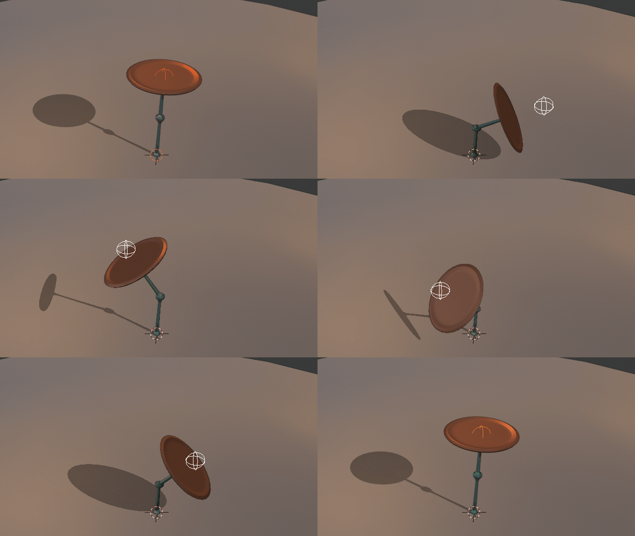
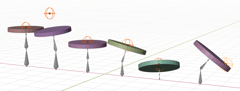
Here is a sketch ↓. Note that this is NOT rigged, it's just posed by hand to illustrate possible cases. I really have no experience with armatures so, if the answer uses a completely different setup, it's fine! (I added a third bone so that it could stay always the same size, but it's probably unnecessary. The first two bones have always the same proportions, so that the rotation pivot is always roughly half-way)

Walktrhough of the cases: the first plate is fully Z-extended, no rotation. The second is rotated to follow the Empty, but can't extend anymore because of the Z-height constraint. The third is compressed because the empty is closer to the origin. The fourth and fifth are compressed and tilted. The sixth is compressed and tilted, but the tilt has stopped due to the rotation constraint.

enter image description here

How do I set up this armature, so that once this is set up, one just has to move the empty around? What parenting relations, constraints and bone constraints are needed?

$\endgroup$

1 Answer 1

2
$\begingroup$

enter image description here

Disclaimer: This solution is not quite geometrically perfect, it doesn't take into account the disk radius and angle when adjusting the height to the target, so the disk doesn't necessarily touch the target at close ranges, but otherwise it seems to work, and ended up being relatively simple.

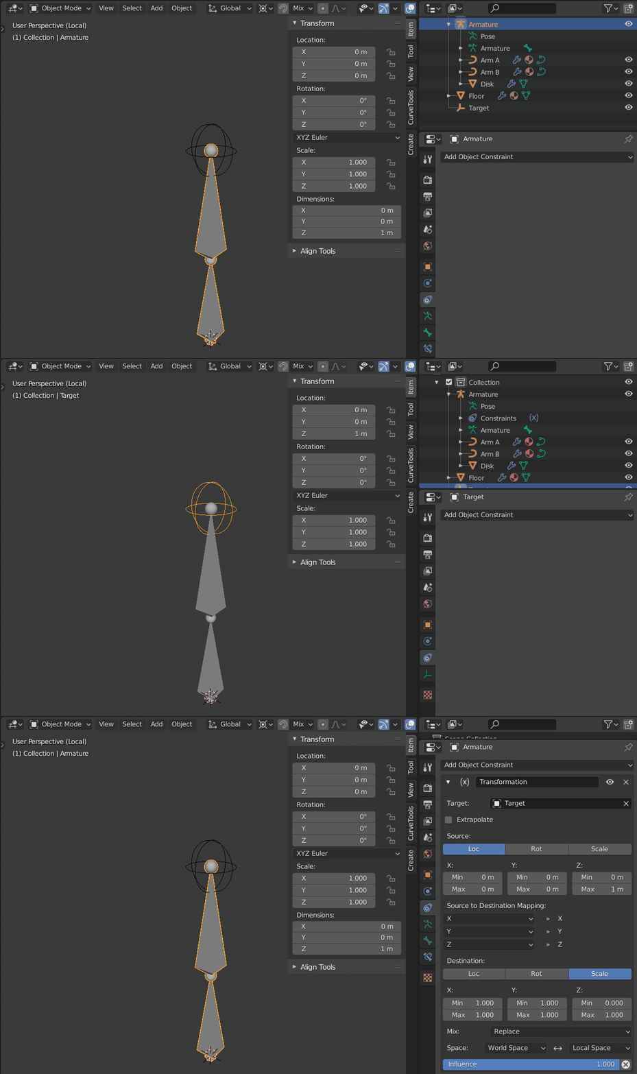
Just setup a single armature with two bones, so that the middle hinge is at half the whole height of the armature. In this case the armature is 1 unit high, so the tail of the second bone is at $0.5$ units in Z.

Create your $Target$ empty exactly at the tip of the second bone.

Add a single Transform constraint to the whole armature, and set it up to transform the Z location of the source object into Scale transform of the armature, and pick the $Target$ object as source.

enter image description here

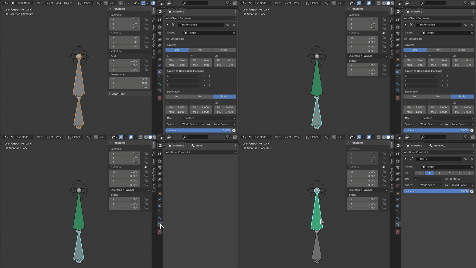
Getting the right values was sort trial and error, but since the armature is 1 unit high, I suspect the min and max values for both source Z coordinate are respectively $0$ and $1$. Set the max scale to whatever height you want to limit the arms to; set space from World to Local.

Now enter Edit Mode in your armature, select the tip bone and add a bone constraint of the Damped Track type and point it to the same $Target$ empty. Track with Y and set Z as Up. You may also want to add a Limit Rotation to bound it to the desired values.

enter image description here

And is about it for the setup. Just create your disk object and parent it to the tip bone (not the whole armature). Make sure to add a Limit Scale constraint with all axis set to $1.0$ so it doesn't change size with target height.

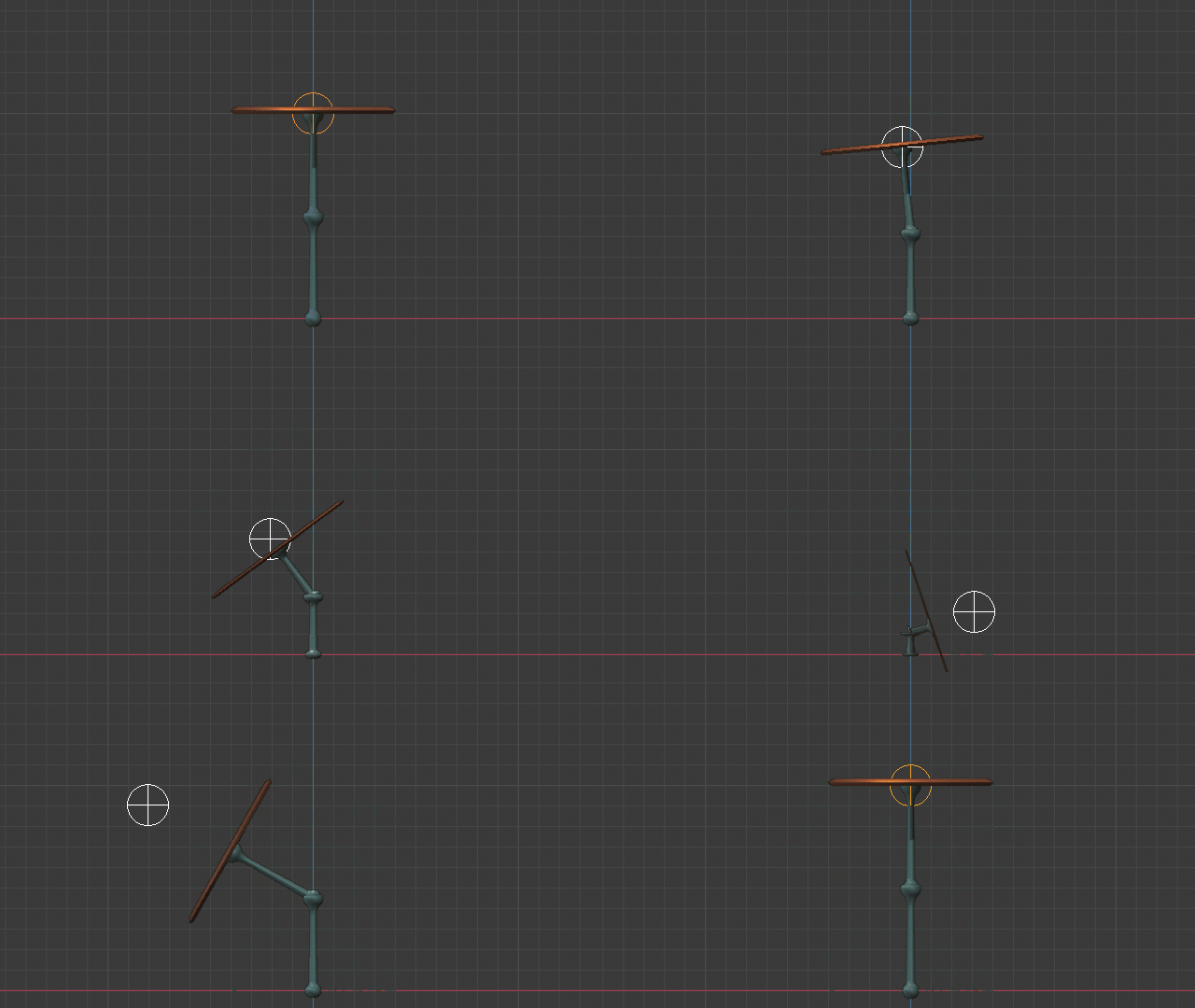
Moving the $Target$ empty around should give you the effect you want while always bending at the middle hinge point.

enter image description here

$\endgroup$
4
  • $\begingroup$ This looks great! I haven't tested it out yet but the gif is quite telling already! Thanks. There are a couple of requirements that haven't been addressed (1. the plate shouldn't deform; 2. the angles should be constrainable), but I think I can figure those one out. I'll report later :) $\endgroup$
    – Nicola Sap
    Commented Sep 18, 2019 at 8:03
  • $\begingroup$ Ah you are right, I was aware of the deformation requirement but didn't notice it until now. The disk does seem to be scaling on local Z, but it should be easy to solve. Either add a Limit Scale constraint, or I believe I saw an option for parenting to armature with no scaling, IIRC. Constrained or stepped angles I don't know how to make, not sure they are possible in Blender, at least without drivers $\endgroup$ Commented Sep 18, 2019 at 9:29
  • $\begingroup$ I re-read you question and now I'm in doubt. Did you mean you require the angles to move in 20 degree increments (stepped movement), or do you mean that the dish angle total shouldn't go more than 20º to each side from vertical "upwars pointing" position? Stepped progression is probably hard to achieve in Blender, but limiting should be as easy as adding a Limit Rotation constraint to the tip bone. $\endgroup$ Commented Sep 18, 2019 at 9:38
  • $\begingroup$ I just emant to limit the total range, so totally doable! I tested your answer and it works perfectly. I only added a Limit rotation: X (70-110), Y (-20,20). I suggest changing "Track to" to "Damped track", which reduces torsions around Z. $\endgroup$
    – Nicola Sap
    Commented Sep 18, 2019 at 11:44

You must log in to answer this question.

Not the answer you're looking for? Browse other questions tagged .