2
$\begingroup$

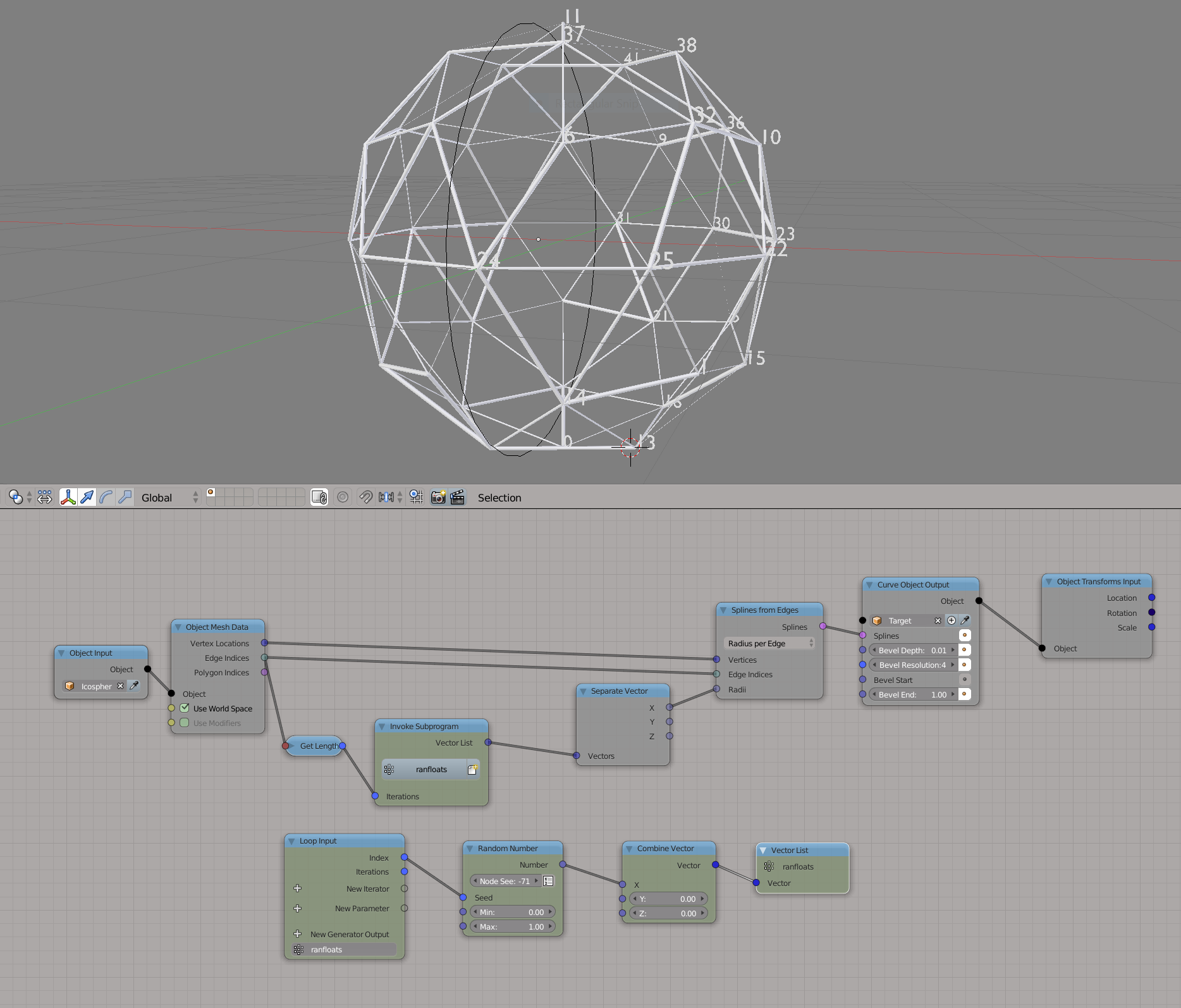
I am trying to create a scene where a list of spheres are positioned onto the verts of a hidden icosphere, and as I move an empty through the icosphere, the visibility of the balls is toggled, and then as each sphere is revealed, splines will grow out to join them (probably using the Bevel End value), following the edges of the icosphere.

I've solved the problem of revealing the spheres as I move the empty, but I'm stuck on the splines part.

I've already created a version of the scene where all the splines are used to create a single curve object and the Bevel End value was used to grow all the splines at once.

Please see this video for what I have so far: https://www.dropbox.com/s/7n3nfqkm1czca2q/Blender_%20%5BD__Data_Dropbox_3D_T3DF__Personal_David%20G_AnimationNodes_bally-ball-plexus.blend%5D%2020_02_2018%2013_21_21.mp4?dl=0

What I want to have is each of the splines grow as their respective spheres are revealed. I know I could instance a bunch of curve objects, equal to the number of edges. In this case, though, all their origin points would be at the same place (0,0,0), and so an effector object wouldn't help, nor would I have the curve objects in any sort of spatial order with which I could use a falloff profile on their individual bevel ends.

I've seen that I can individually effect the splines of a single curve object, as shown below, but I haven't been able to figure out how to do that based on proximity to something else, or even in any particular order.

enter image description here

Have I made sense here?

Any ideas?

Thanks

$\endgroup$

2 Answers 2

3
$\begingroup$

Animation Nodes have a node called Trim Spline Node which can be used to dynamically trim splines. There are certain complications, however, if one decided to use this node:

  1. Edges are not directed, so you may observe some splines growing outward from a vertex and other splines inward toward a vertex.
  2. There no easy way to determine which edges belong to which vertex, in other words, there is no way to determine the locations of the points of the spline to derive the trim node by.

Thus we are forced to to use a more advanced approach, but no worries, it is just as easy.

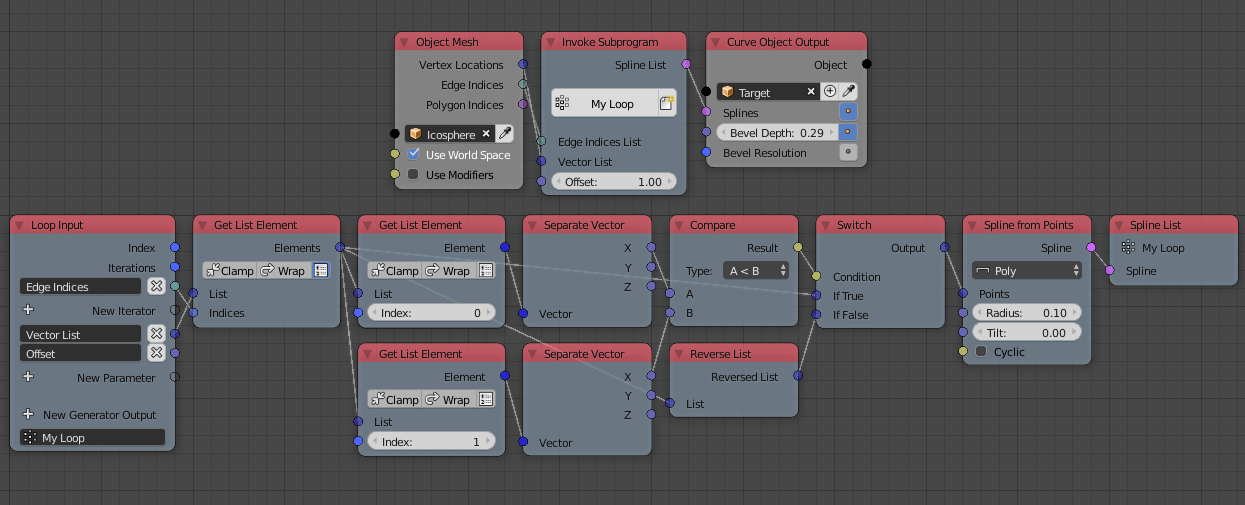
First, we loop over edges, get the vertices locations at the indices of the edge indices, sort the vertices in the direction of the animation, I can see that your animation is from the left to right, so we check if the $x$ location of the first vertex is larger than that of the second, if it is, we reverse the list such that the first vertex becomes the one that is closest to the initial location of the animated effector, then we create a spline from those vertices.

Node Tree 1

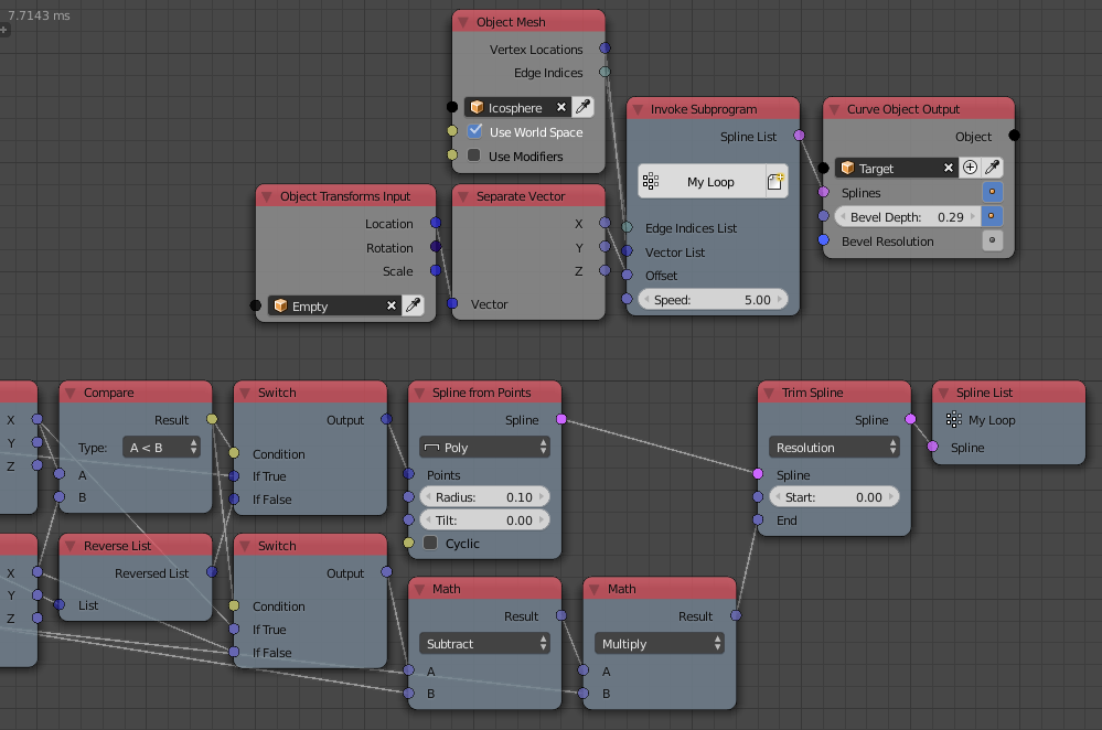
Second, we trim the output splines based on the distance between the effector and the initial vertex of the spline, since your animation is along the $x$ axis, the distance is simply the difference between the $x$ locations of the effector and the vertex:

node Tree 2

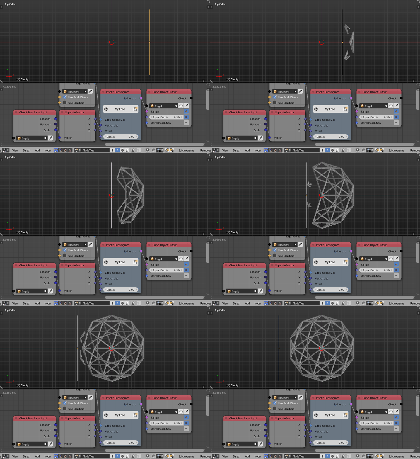
Which results in:

Result

Notice that the trim node shouldn't be used here, because the spline is just a line so a linear combination between both vertices of the line would yield the same effect, but I just wanted to show you how trim node can be used.

$\endgroup$
9
  • $\begingroup$ Thank you so much for that, I had not looked at the Trim Spline node. I also came up with a solution of my own using a different method which I'll show below. $\endgroup$ Commented Feb 28, 2018 at 14:06
  • $\begingroup$ what do you think are the pros and cons of our respective solutions? Your solution achieves the same result with a single curve object, rather than my solution which creates N number of objects. $\endgroup$ Commented Feb 28, 2018 at 14:16
  • $\begingroup$ One clarification on your screenshots please - in the second screenshot, you have a Math-Multiply node, I can't see where Input B is being linked from. $\endgroup$ Commented Feb 28, 2018 at 14:20
  • $\begingroup$ @DavidGilson It is being linked to the speed input of the loop. It seems your solution doesn't handle the direction of the spline growth, it may work for this mesh, but now for every mesh. $\endgroup$
    – Omar Emara
    Commented Feb 28, 2018 at 15:08
  • $\begingroup$ Omar, sorry, I don't see a "speed" input in those screenshots. $\endgroup$ Commented Feb 28, 2018 at 15:50
1
$\begingroup$

I've accepted the answer from @Omar Ahmad, but I also wanted to show the solution I came up with.

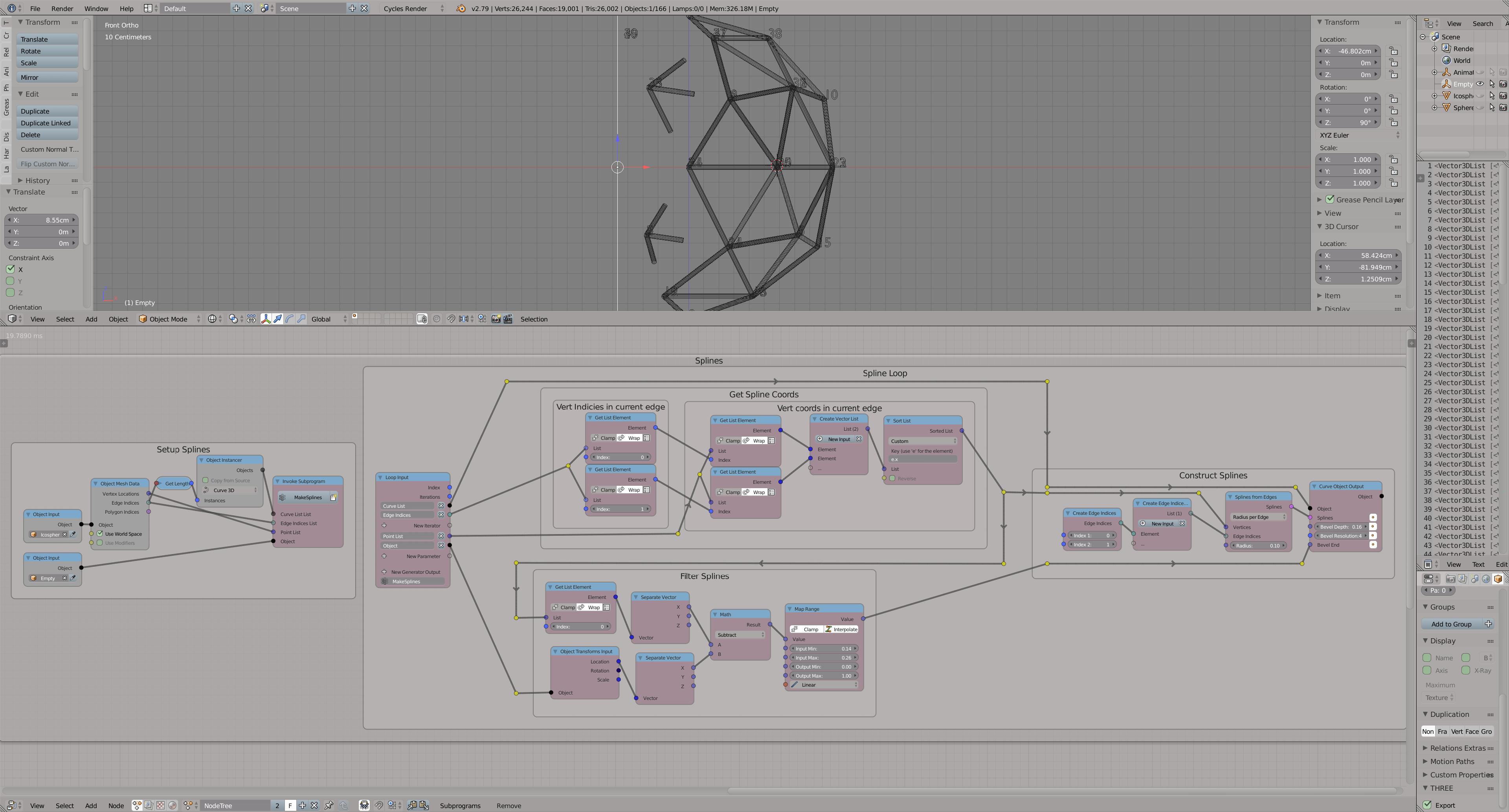
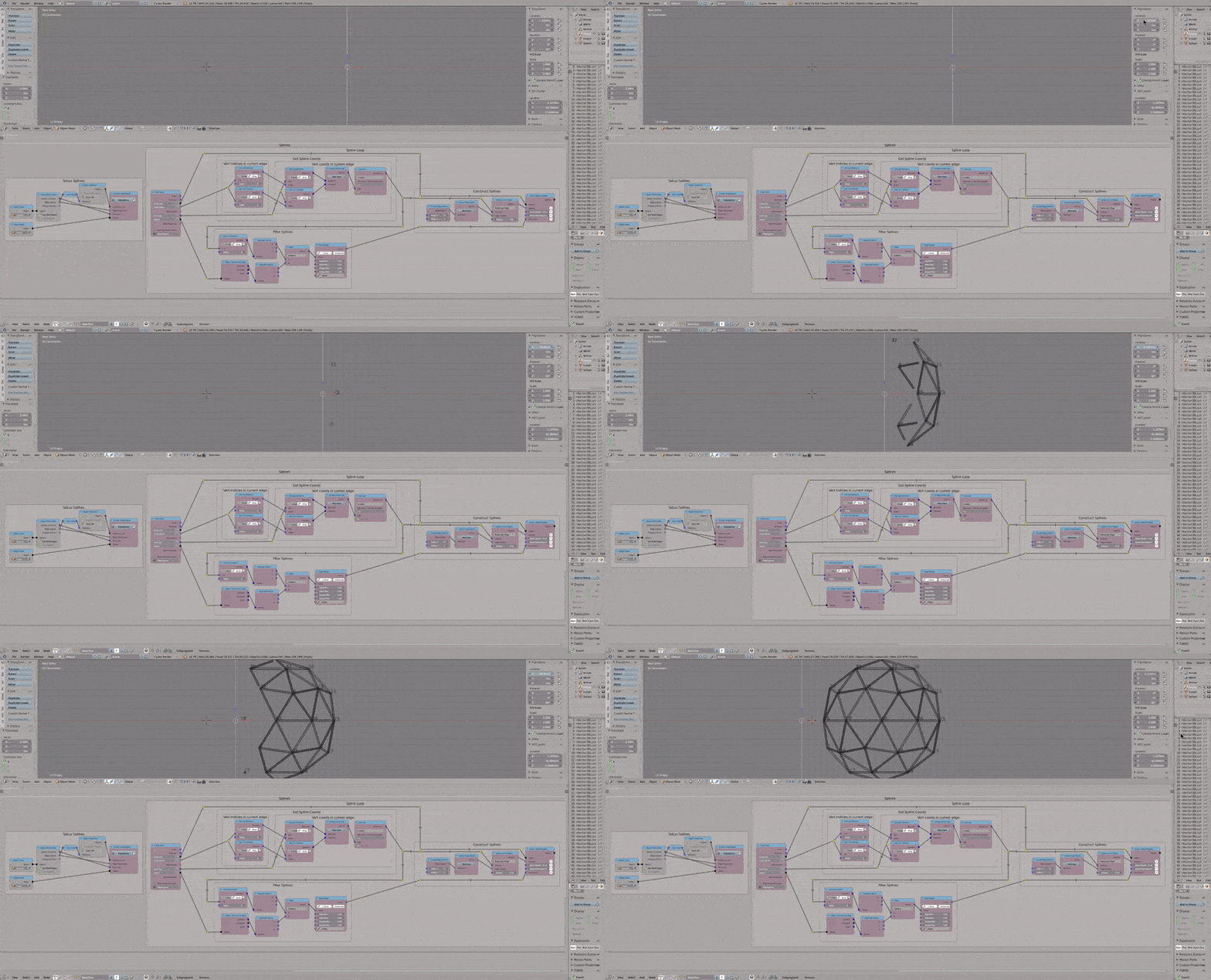
Rather than using the trim spline node, I instanced a bunch of curve objects, and fed each single edge into each of them, and then set their bevel end value based on the distance from the effector object. Here's an animated gif and a hi-res screenshot showing my node setup

enter image description here

enter image description here

$\endgroup$
1
  • $\begingroup$ Some notes to improve your solution. In the Get Spline Coords part, you can can just get both locations through the list option in the Get list node like I did in my solution. The Object Transfrom output and the separate vector after it should be outside the loop (They are constants and should be computed a single time). Instead of using Spline From Edges use Spine From Points, it is easier and more efficient. Don't use the map range node, especially not inside a loop, use math nodes instead. $\endgroup$
    – Omar Emara
    Commented Feb 28, 2018 at 15:11

You must log in to answer this question.

Not the answer you're looking for? Browse other questions tagged .