added 1402 characters in body
Source Link
Nathan
  • 25.2k
  • 1
  • 24
  • 72

The distance to the camera depends on the actual vertex being evaluated. One vert may be very close to the cameraSo originally, while another is very far. So you don't want to do itI recommended doing this with distance to object drivers; you need to do itgeometry nodes, and you've had some trouble with modifiersthat. (Because distance to camera interpolates linearly between verts In preparing you a better answer, it's perfectly safeI've had nothing but trouble with trying to do this on a per-vert basis.)

There are two waysget geometry nodes to do this. One uses vertex weight proximity, vertex weight editgive me the proper materials, and possibly vertex weight mix before your solidify. ThisGN instanced materials is the painful but performant way. I won't demonstrate this, just mentioningone of those things that it is possible and gets better performance. It relies on the fact that therestill changing with every release (and is a max distance possible for your camera-- its far clip-- and uses that to rescale the vertex groupcurrently pretty wicked bugged.

The easier way to set it up is to use geometry nodes) At the same time, because geometry nodes handle attributesI realized that are outsideI was overthinking the 0alternatives,1 range-- and distance to camera is likelythey're not really hard to be outside of that rangeimplement. We can figure that out and then duplicate our geometry So instead of doing it with GN, movinglet's do it along normals a distance proportional to distance to camera:with regular old modifiers.
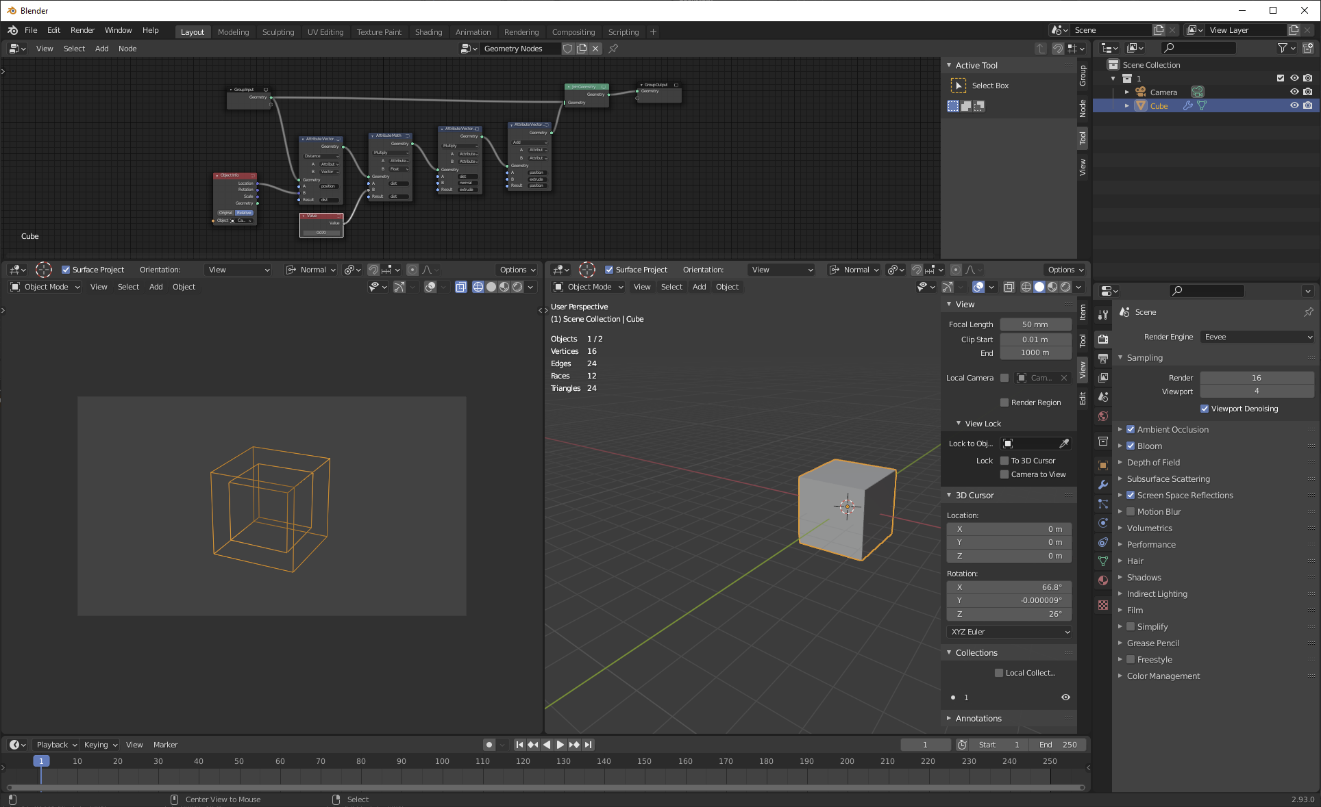
enter image description here You've indicated in comments that your end goal for this is outlining, so let's work with an outlining example.

  1. Select your object and make sure that scale is applied. What I am demonstrating will not work with unapplied scale, even with inherited scale. You can do some tricks to make it work with uniform unapplied scale, but it will never ever work with non-uniform scale.

  2. Make a new VG for it, call that new VG "prox". Assign all vertices to "prox" at weight 1.0.

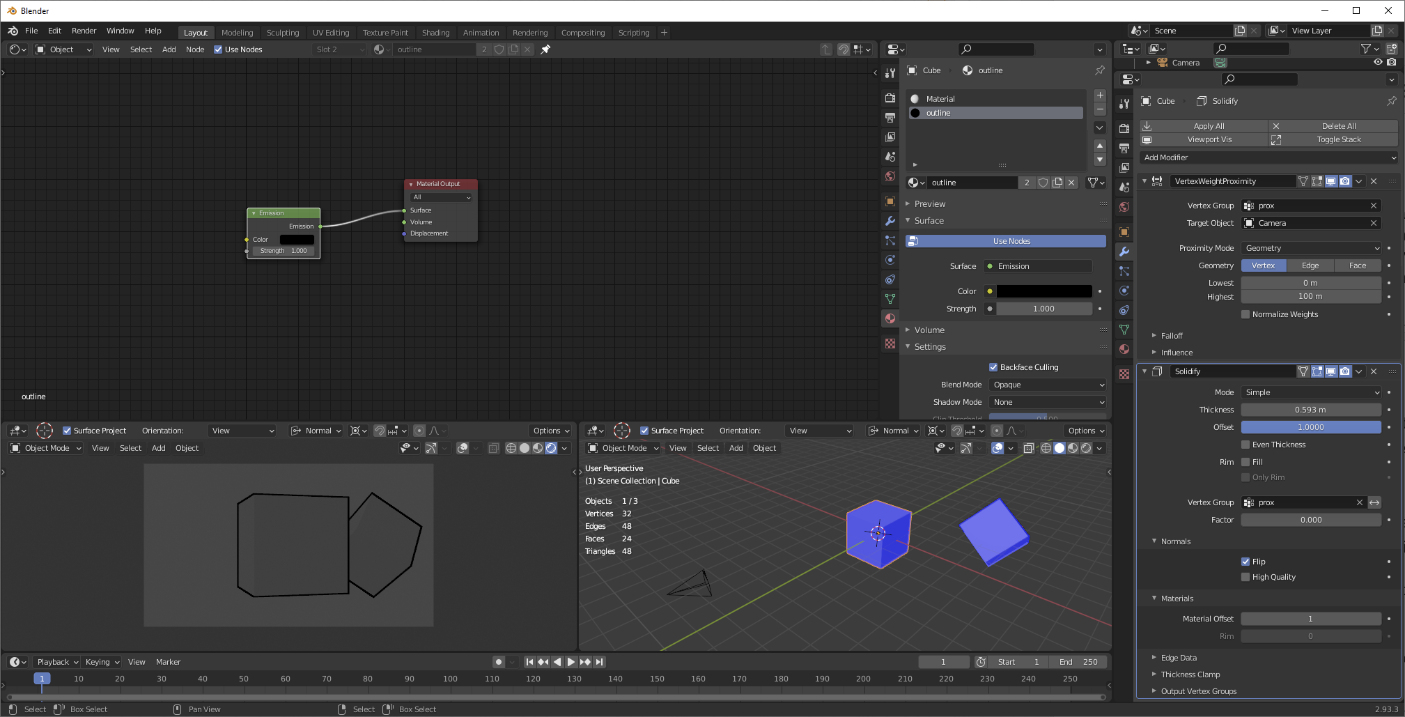
  3. Give your object a vertex weight proximity modifier. Set the target object to your camera. Set the vertex group to "prox". Set the proximity mode to geometry/vertex. Set the lowest weight to 0m and the highest weight equal to the far clip of your camera (default, 100m.)

  4. Give your object a solidify modifier. Set the offset to 1.0, disable rim fill, enabled flipped normals, and give it an appropriate material offset so that the solidified mesh acquires your outline material (talked about in a little more depth below.) Set the vertex group to "prox" and then, from your camera's perspective, set the thickness to eye.

Now, there are a few concerns to be aware of here you need an outline material. First For mine, notice that there is no solidify modifier. A solidify modifier needs to use VGsrendering in the 0,1 rangeEevee, and I don't want to use that range for simplicity's sake. That's okay, the GN emulate the solidify alongjust made a black emission material with how far to do itbackface culling enabled. But where you can have issues is that this means that you can't create Because my object had only a simplesingle material offset. Doing this in real-life, to do outlining (which is probably what you wantbefore creating the outline material, it's what I wanted in learning how to do this), you probably don't wantset the solidify Material Offset to join1. If you're ever having trouble with your original object; you want youran outline to be its own separate object, referencing your original geometry, with its own "outline" material, and assigning a material index atremember that the end of its nodes to make it use its own material rather than thosedirection of its sources. (This actually ends up being more convenient, byyour normals is the way-- you can outline entire collections rather than objectsmost important thing, and youthat different directions of normals can put the outlines on their own collectionsbe made to easily disable for performancework, just in different ways.)

The other thing to be careful of isPic demonstrating all that keeping:

enter image description here

Now let's zoom out the same screen-space thickness isn't just a function of distance to camera, but of field of view (camera focal length and sensor size) as well. If you change your field of view without changing your thickness, the thickness won't stay:

enter image description here

Outlines are the same width. It is possible to compensate for this, using driven values in your GN to calculate FoV

Here's a file so you can play with the camera and then compensate for changes, but I haven't demonstrated here.see it working:

Notes:

  1. When doing it this way, geometry that spans the far clip distance won't really work properly. This will probably be unnoticeable in practice, but it's possible to create theoretical situations that aren't right. (Really, any geometry that spans the far clip won't look right, so the fact that the outline also won't be right doesn't much matter.)

  2. SS thickness is not just a function of distance to camera, but of FoV as well. You can create a driver to change the thickness linearly as FoV increases, but it's kind of a pain because you have to figure FoV from sensor size and focal length. I'm assuming you won't be changing FoV in any animations.

  3. The way that these kinds of outlines work, the thickness of the line is not a single value-- the thickness, in pixels, depends not just on your solidify modifier's thickness, but on the angle of the face relative to your camera as well. What we're doing is establishing a constant maximum outline thickness. In practice, your outlines will vary from this zero to this maximum. Again, this does not depend on distance, but on relative angle.

  4. I mentioned that this will potentially work with unapplied uniform scale. Solidify thickness is in object space not world space, so if you want it to work with unapplied scale, create a driver for your solidify thickness that divides the thickness by your object's scale (x,y, or z, because if it's uniform scale, they're all the same.)

The distance to the camera depends on the actual vertex being evaluated. One vert may be very close to the camera, while another is very far. So you don't want to do it with distance to object drivers; you need to do it with modifiers. (Because distance to camera interpolates linearly between verts, it's perfectly safe to do this on a per-vert basis.)

There are two ways to do this. One uses vertex weight proximity, vertex weight edit, and possibly vertex weight mix before your solidify. This is the painful but performant way. I won't demonstrate this, just mentioning that it is possible and gets better performance. It relies on the fact that there is a max distance possible for your camera-- its far clip-- and uses that to rescale the vertex group.

The easier way to set it up is to use geometry nodes, because geometry nodes handle attributes that are outside the 0,1 range-- and distance to camera is likely to be outside of that range. We can figure that out and then duplicate our geometry, moving it along normals a distance proportional to distance to camera:

enter image description here

Now, there are a few concerns to be aware of here. First, notice that there is no solidify modifier. A solidify modifier needs to use VGs in the 0,1 range, and I don't want to use that range for simplicity's sake. That's okay, the GN emulate the solidify along with how far to do it. But where you can have issues is that this means that you can't create a simple material offset. Doing this in real-life, to do outlining (which is probably what you want, it's what I wanted in learning how to do this), you probably don't want to join with your original object; you want your outline to be its own separate object, referencing your original geometry, with its own "outline" material, and assigning a material index at the end of its nodes to make it use its own material rather than those of its sources. (This actually ends up being more convenient, by the way-- you can outline entire collections rather than objects, and you can put the outlines on their own collections to easily disable for performance.)

The other thing to be careful of is that keeping the same screen-space thickness isn't just a function of distance to camera, but of field of view (camera focal length and sensor size) as well. If you change your field of view without changing your thickness, the thickness won't stay the same. It is possible to compensate for this, using driven values in your GN to calculate FoV and then compensate for changes, but I haven't demonstrated here.

So originally, I recommended doing this with geometry nodes, and you've had some trouble with that. In preparing you a better answer, I've had nothing but trouble with trying to get geometry nodes to give me the proper materials, and GN instanced materials is one of those things that is still changing with every release (and is currently pretty wicked bugged.) At the same time, I realized that I was overthinking the alternatives, and they're not really hard to implement. So instead of doing it with GN, let's do it with regular old modifiers.

You've indicated in comments that your end goal for this is outlining, so let's work with an outlining example.

  1. Select your object and make sure that scale is applied. What I am demonstrating will not work with unapplied scale, even with inherited scale. You can do some tricks to make it work with uniform unapplied scale, but it will never ever work with non-uniform scale.

  2. Make a new VG for it, call that new VG "prox". Assign all vertices to "prox" at weight 1.0.

  3. Give your object a vertex weight proximity modifier. Set the target object to your camera. Set the vertex group to "prox". Set the proximity mode to geometry/vertex. Set the lowest weight to 0m and the highest weight equal to the far clip of your camera (default, 100m.)

  4. Give your object a solidify modifier. Set the offset to 1.0, disable rim fill, enabled flipped normals, and give it an appropriate material offset so that the solidified mesh acquires your outline material (talked about in a little more depth below.) Set the vertex group to "prox" and then, from your camera's perspective, set the thickness to eye.

Now you need an outline material. For mine, rendering in Eevee, I just made a black emission material with backface culling enabled. Because my object had only a single material before creating the outline material, I set the solidify Material Offset to 1. If you're ever having trouble with an outline material, remember that the direction of your normals is the most important thing, and that different directions of normals can be made to work, just in different ways.

Pic demonstrating all that:

enter image description here

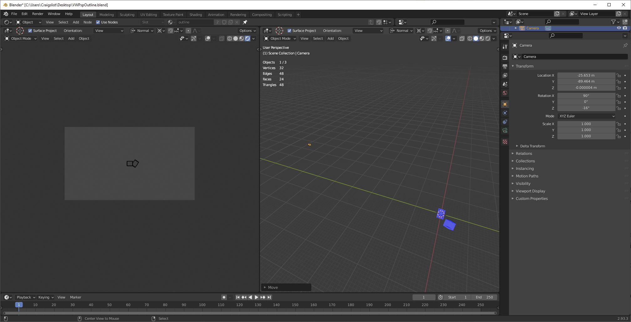
Now let's zoom out the camera:

enter image description here

Outlines are the same width.

Here's a file so you can play with the camera and see it working:

Notes:

  1. When doing it this way, geometry that spans the far clip distance won't really work properly. This will probably be unnoticeable in practice, but it's possible to create theoretical situations that aren't right. (Really, any geometry that spans the far clip won't look right, so the fact that the outline also won't be right doesn't much matter.)

  2. SS thickness is not just a function of distance to camera, but of FoV as well. You can create a driver to change the thickness linearly as FoV increases, but it's kind of a pain because you have to figure FoV from sensor size and focal length. I'm assuming you won't be changing FoV in any animations.

  3. The way that these kinds of outlines work, the thickness of the line is not a single value-- the thickness, in pixels, depends not just on your solidify modifier's thickness, but on the angle of the face relative to your camera as well. What we're doing is establishing a constant maximum outline thickness. In practice, your outlines will vary from this zero to this maximum. Again, this does not depend on distance, but on relative angle.

  4. I mentioned that this will potentially work with unapplied uniform scale. Solidify thickness is in object space not world space, so if you want it to work with unapplied scale, create a driver for your solidify thickness that divides the thickness by your object's scale (x,y, or z, because if it's uniform scale, they're all the same.)
Source Link
Nathan
  • 25.2k
  • 1
  • 24
  • 72

The distance to the camera depends on the actual vertex being evaluated. One vert may be very close to the camera, while another is very far. So you don't want to do it with distance to object drivers; you need to do it with modifiers. (Because distance to camera interpolates linearly between verts, it's perfectly safe to do this on a per-vert basis.)

There are two ways to do this. One uses vertex weight proximity, vertex weight edit, and possibly vertex weight mix before your solidify. This is the painful but performant way. I won't demonstrate this, just mentioning that it is possible and gets better performance. It relies on the fact that there is a max distance possible for your camera-- its far clip-- and uses that to rescale the vertex group.

The easier way to set it up is to use geometry nodes, because geometry nodes handle attributes that are outside the 0,1 range-- and distance to camera is likely to be outside of that range. We can figure that out and then duplicate our geometry, moving it along normals a distance proportional to distance to camera:

enter image description here

Now, there are a few concerns to be aware of here. First, notice that there is no solidify modifier. A solidify modifier needs to use VGs in the 0,1 range, and I don't want to use that range for simplicity's sake. That's okay, the GN emulate the solidify along with how far to do it. But where you can have issues is that this means that you can't create a simple material offset. Doing this in real-life, to do outlining (which is probably what you want, it's what I wanted in learning how to do this), you probably don't want to join with your original object; you want your outline to be its own separate object, referencing your original geometry, with its own "outline" material, and assigning a material index at the end of its nodes to make it use its own material rather than those of its sources. (This actually ends up being more convenient, by the way-- you can outline entire collections rather than objects, and you can put the outlines on their own collections to easily disable for performance.)

The other thing to be careful of is that keeping the same screen-space thickness isn't just a function of distance to camera, but of field of view (camera focal length and sensor size) as well. If you change your field of view without changing your thickness, the thickness won't stay the same. It is possible to compensate for this, using driven values in your GN to calculate FoV and then compensate for changes, but I haven't demonstrated here.