6
$\begingroup$

I have a sphere (world) that I want to reveal the night lights on. I can use a normal node and manually rotate the DOT product, then I use this as a factor mix between Day time shader and Night time shader.

But I want an interactive version so I only have to move the light in 3D view.

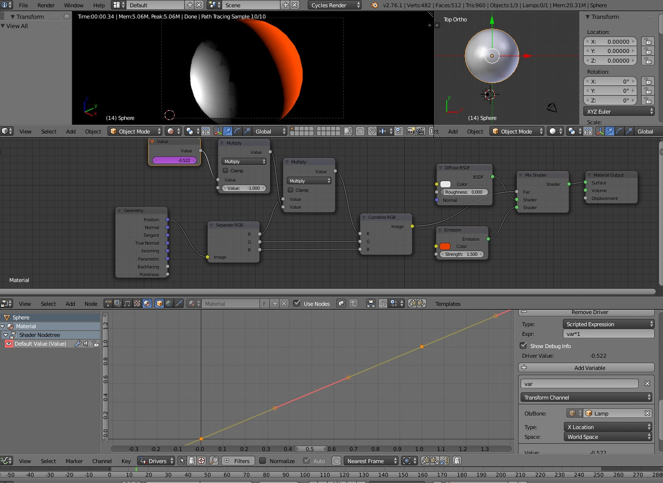
I guessed that maybe I could take the Lamp's position as a driver value and modify the position normal of my sphere. See screeny:

enter image description here

But I can't figure the math to take all angles into account.

$\endgroup$
4
  • $\begingroup$ I have a similar setup in my .blend here, but based on the rotation of a sun lamp rather than position.. At the very least you could use a track to constraint or something to convert the position to a rotation, in case it's not possible to do the necessary maths in the driver itself $\endgroup$
    – gandalf3
    Commented Feb 18, 2016 at 3:23
  • $\begingroup$ Yeah thanks for the tip, I just tried a rotating sun lamp but couldn't express an opposite value for some reason (being innumerate I guess) $\endgroup$
    – 3pointedit
    Commented Feb 18, 2016 at 3:45
  • $\begingroup$ This question has two good answers. One of them should be marked as correct. $\endgroup$
    – dval
    Commented Feb 23, 2016 at 15:47
  • $\begingroup$ I'm not sure that I can choose one, as they both approach the problem from different directions. One is driver based, the other node based. Both are important to understand. I would choose the smaller one but the driver answer is probably more important to understand. $\endgroup$
    – 3pointedit
    Commented Feb 24, 2016 at 2:35

2 Answers 2

8
$\begingroup$

Turns out this is pretty easy to do. "Easy" as in "you're deprived of doing all the fun math manually" ;)

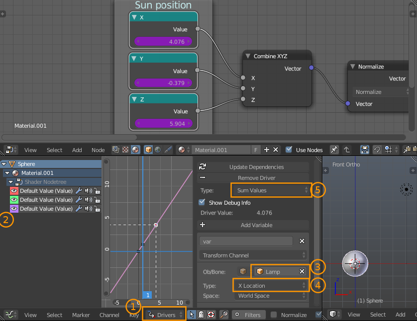
  1. Add three Value nodes (or a single Combine XYZ node) into which drivers can be added. I prefer the three value node approach in case you want to access individual axes later on.
  2. Add drivers to each of the value nodes by right clicking on each and selecting Add Driver.
  3. In the Graph Editor and switch to Drivers mode in the header (1).

    enter image description here

    Ensure that both the object using the material and the value nodes are selected, then repeat the following until all the drivers are set up:

    1. Select the next driver in the driver list on the left of the graph editor
    2. Select the driver target, in this case the point lamp (you can press E while hovering over this field, then click on the lamp in the 3D view for a speedier selection workflow)
    3. Set the transform type to X, Y, or Z Location, making sure to pick the right one for each driver
    4. Set the driver type to Sum Values. We don't need any fancy scripted python stuff, and avoiding the Scripted Expression setting will prevent the drivers from being disabled for security reasons.
  4. If you put the drivers on value nodes, connect them to a Combine XYZ node.

  5. Add a Vector Math node set to Normalize and connect the Combine XYZ node. This will ensure the values from the driver are scaled down to the 0..1 range.
    Note that only the first input of the normalize node is used, so I've hidden the extraneous sockets with ⎈ CtrlH.
  6. Take the Dot Product of the normalized location and the object's normals (obtained from either a Texture Coordinate or Geometry node) via another Vector Math node.
  7. Adjust the scalar result of the dot product to suit our needs better with some math nodes and a colorramp:

    enter image description here

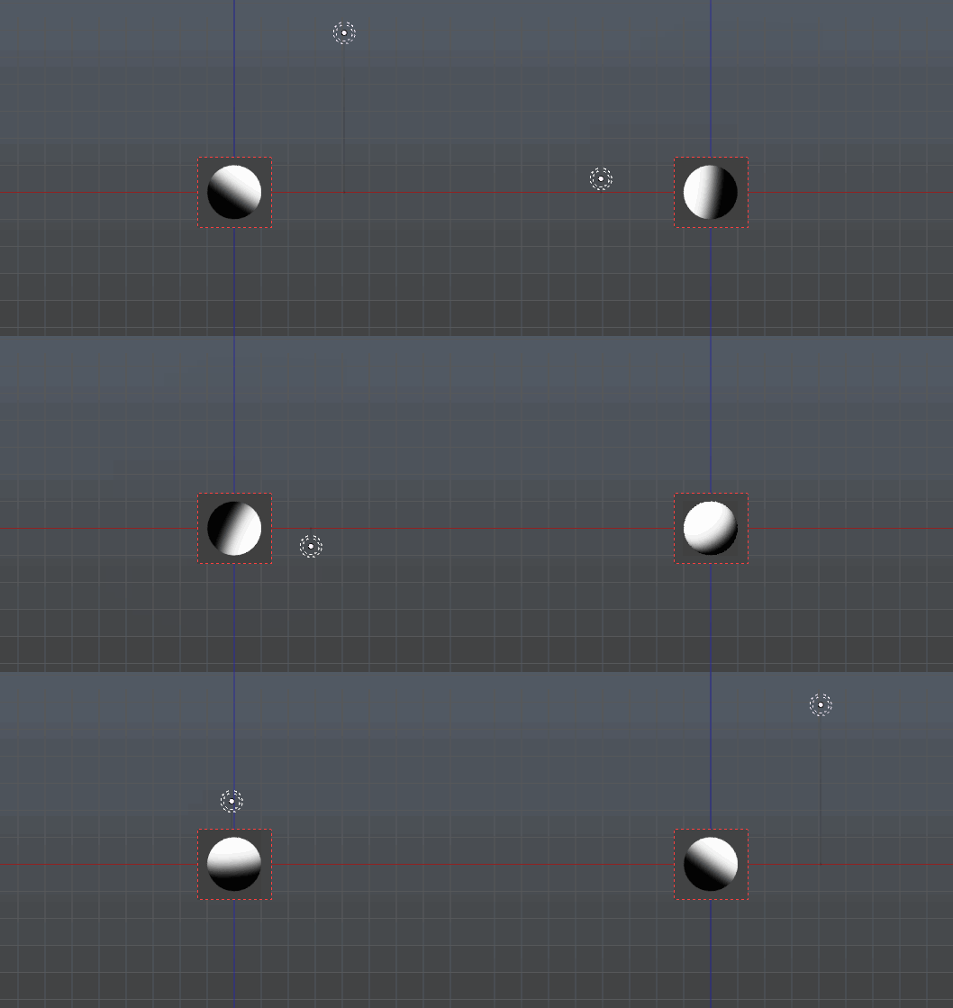
The resulting gradient should update in real time:

enter image description here

$\endgroup$
2
  • $\begingroup$ Thank you so much, seems like the sort of thing an addon would be good at setting up. Really glad that I asked now. $\endgroup$
    – 3pointedit
    Commented Feb 18, 2016 at 8:31
  • $\begingroup$ Turns out that in Blender 2.8 Eevee, currently Texture (alt) Object Position is not available so this is the working solution for Eevee ;-) $\endgroup$
    – 3pointedit
    Commented Apr 26, 2019 at 1:24
3
$\begingroup$

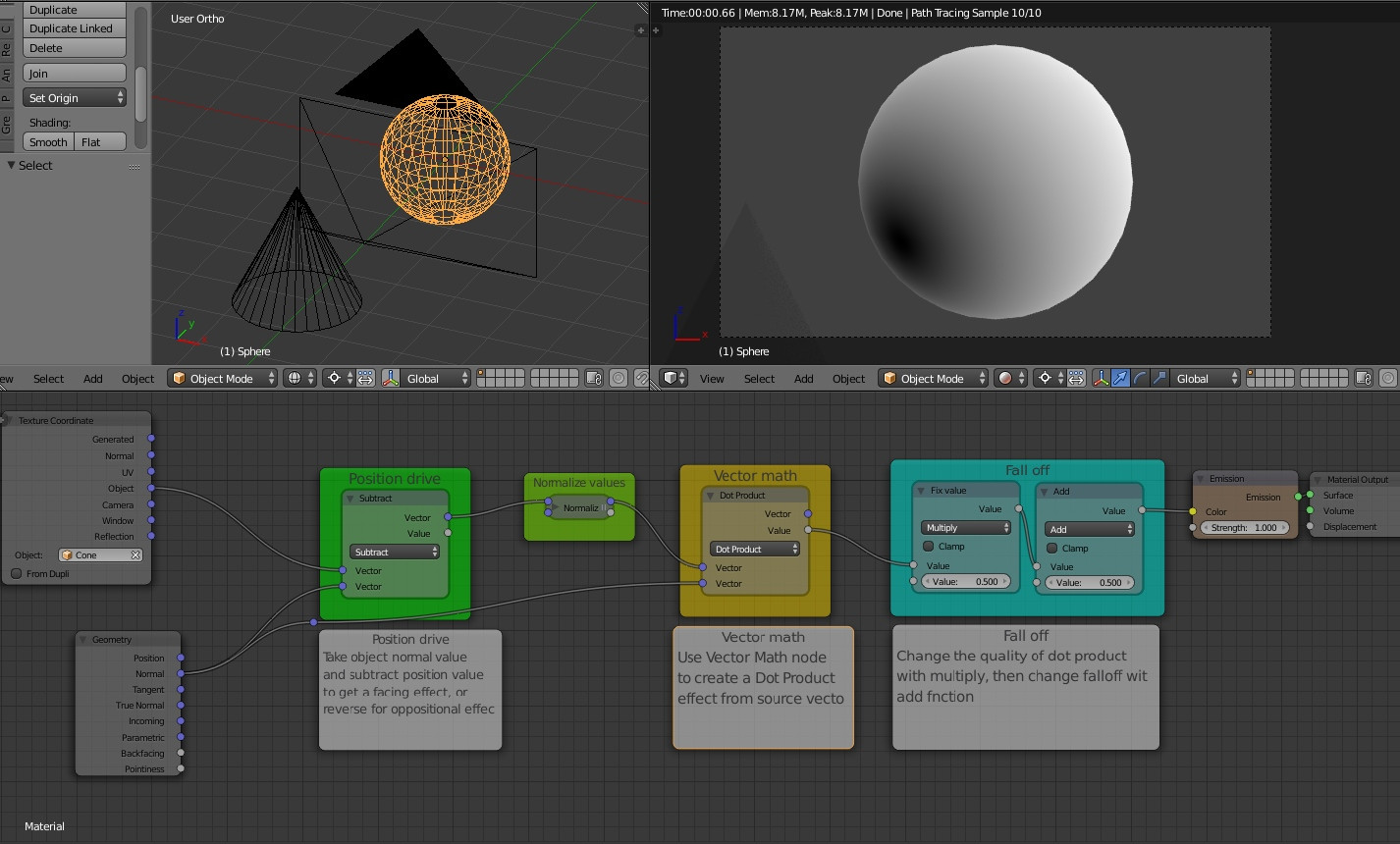
A further answer was provided by Viktor Mukayev https://twitter.com/vitos1k who suggested using the texture co-ordinates node to produce a Dot Product:

enter image description here

$\endgroup$

You must log in to answer this question.

Not the answer you're looking for? Browse other questions tagged .